News

Jack pump VFD selection for an off-grid oilfield: one drive per well, or one drive for the field

2026-10-14 0 Leave me a message

Jack pump VFD selection on this field turned on one question: how many drives to install. Sixteen beam pumping units run from centralized diesel generation on site, and three proposals were made before the order.

Item

Value

Site

Onshore oilfield, Madagascar

Lift method

16 beam pumping units (jack pumps)

Motor rating

15 kW per well, 240 kW for the field

Supply

Off-grid, centralized diesel generation on site

Supply nameplate

415 V / 50 Hz

Measured at the wellhead

382 V / 50.2 Hz, about 8% below nameplate

Starting current

6 to 8 times rated current, per motor

Site constraints

Large site area, production cannot stop

Installed configuration

16 x 15 kW VFD, one per well, one RTU per well


The selection inputs are few: the number of wells, the motor rating, the supply, the cable length to each well, and the production constraint. Everything else follows from those.

The first decision: how many drives

A VFD has one output. Every motor connected to that output runs at the same frequency, so a single drive can run the whole field as one group. This is standard practice for multi-motor loads, and it is the cheaper architecture: one unit, one output reactor, one motor cable per well. The first two proposals for this field were both built that way.

One output frequency is not a defect in itself. Where the driven machines share one speed, one drive on a shared bus is the correct arrangement and not a compromise.

One drive per well costs more and uses more wiring.

Cost decides this question only when the process allows the group arrangement. For a field that has to produce every hour, it does not.

One shared drive: advantages and limits

A group drive carries sixteen motors on one output. The field then needs one unit in place of sixteen, one output reactor, and one set of supply and control wiring.

What it saves

● One unit to buy in place of sixteen, and one unit to commission, to document, to hold spares for and to connect to the control system

● One set of enclosures, so less panel space, less ventilation and less cooling

● Line-side harmonic mitigation bought and installed once, on the supply side of that unit

● Fewer items on site, so routine inspection covers fewer devices

None of these reasons is technical. They are cost and logistics, and they are why the first two proposals on this field were built this way.

Where one frequency is the right answer

● where the driven machines form one process train and have to run in step, such as several motors on one conveyor, one mixer shaft or one pump manifold, a single output frequency is the design intent

● every motor on the output shares one speed reference and one V/f, so load sharing across the group is automatic and no unit drifts away from the others

● the group starts and stops as one event, so the process interlock has one action to handle instead of sixteen

Where one frequency becomes a limit

One output frequency. This field is the other case. Sixteen wells are sixteen independent producers, not one train. A single output frequency gives them one speed and one availability between them. They run together and stop together, and stopping one well for maintenance stops the bus.

Single point of failure. Any fault on the output side, in a motor or in its cable, trips the drive. All sixteen wells stop with it, and the field goes out of production as one unit.

Undervoltage at the far end. Wells are spread across a large site, so motor cables are long and voltage drop accumulates along the run. The motor furthest from the drive sees the lowest voltage, and the gap widens during every start, when current is at its highest.

Motor protection. A drive's built-in overload protection is designed around one motor. With several motors on one output, the total current can stay inside the drive's limit while one motor overheats. Each motor and its cable then need a separate thermal relay or breaker.

Three of the four limits stand whatever the process is. Where the group speed suits the load, the speed is not in question, but a shared bus is still one point of failure, still leaves the far motor at the lowest voltage, and still needs separate overload protection at each motor.

The remaining limit belongs to the process. A control system cannot remove it: an RTU on a shared drive can report status and it can stop the drive, but it cannot stop one well while the others run. Breaking a loaded output circuit arcs, so the drive has to stop before any single well can be isolated.

One drive per well: what it gains, and what it costs

What it gains

● each well runs at its own frequency, so stroke rate and rod load can be set well by well

● one well can stop for maintenance while the other fifteen keep pumping

● a fault in a motor, a cable or a drive stops one well and reaches no further

● the drive can be installed at the wellhead, so the motor cable stays short

● starts can be staggered, which limits the voltage dip on the generation

● overload protection matches one motor, because each drive feeds one motor

● commissioning runs well by well, and the wells not yet converted stay in production

What it costs

● sixteen drives in place of one, which is the highest equipment cost of the two arrangements

● sixteen enclosures, each with its own supply, control and communication wiring, and more devices to commission, to document and to hold spares for

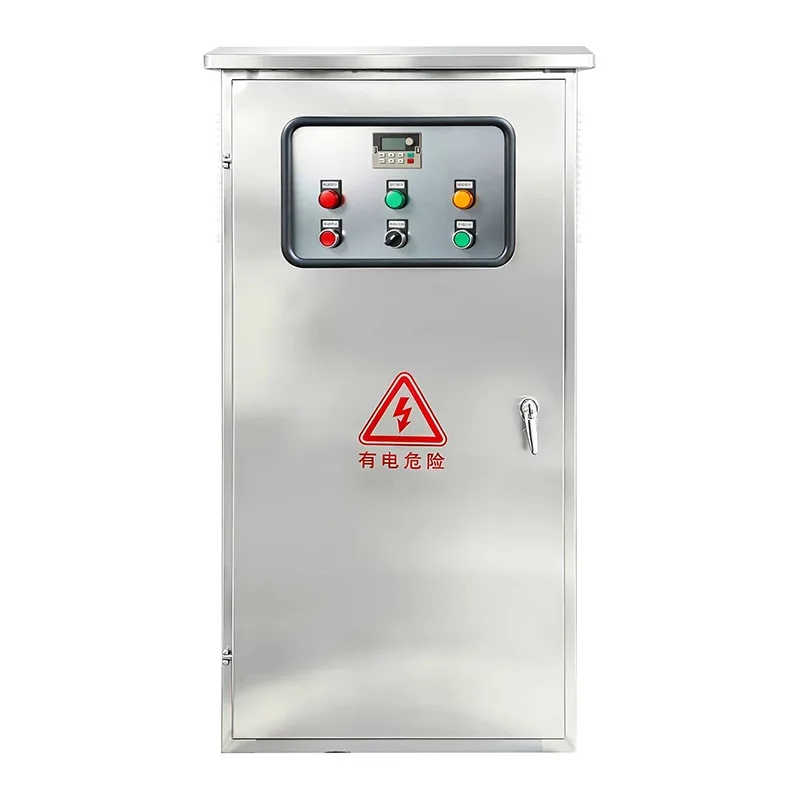
● where a drive is installed at the wellhead, its enclosure has to be rated for dust, ambient heat and weather

● sixteen rectifier front ends in place of one, so line-side harmonic mitigation is applied at more points

● a larger number of components on site. Fault isolation limits the consequence of a failure; it does not reduce the number of items that can fail

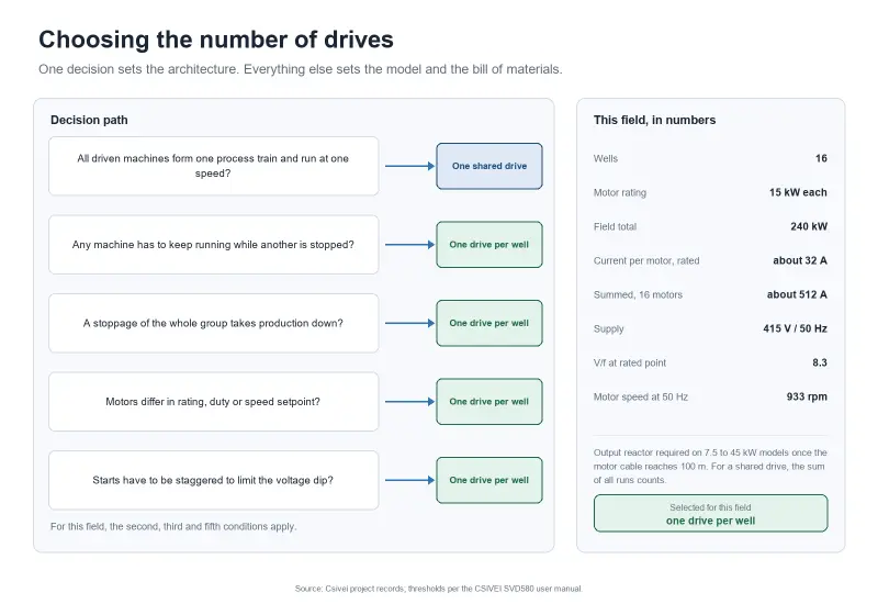
Conditions that decide the arrangement

Condition on site

Arrangement

the driven machines form one process train and run at one speed

one shared drive

any machine has to keep running while another is stopped

one drive per well

a stoppage of the whole group takes production down

one drive per well

motors differ in rating, duty or speed setpoint

one drive per well

starts have to be staggered to limit the voltage dip on the generation

one drive per well


At this site a group stoppage and a live-bus isolation were both unacceptable, so the higher-cost arrangement was taken. Where the process allows a group arrangement, the cheaper one applies.

Sizing a shared drive, where the process allows it

Sizing a shared jack pump VFD starts from the total motor current, not from one motor. A 15 kW motor at 380 V draws about 32 A at rated load, so sixteen wells at rated load come to about 512 A. That figure is the starting point of the calculation, not the rating of the drive.

Two things move the number. A beam pumping unit draws a cyclic load through each stroke, so the running load a group drive carries is not the sum of the nameplate currents held continuously. The peak comes from starting: one motor at six to eight times rated current, added to what the other wells draw at that moment. That transient, together with the generation behind it, is what sets the rating.

The SVD580 series drives multi-motor loads, subject to the cable and protection rules in sections 3 and 7. Those rules, rather than the drive current, are usually what decides whether a shared drive is practical.

The per-well configuration

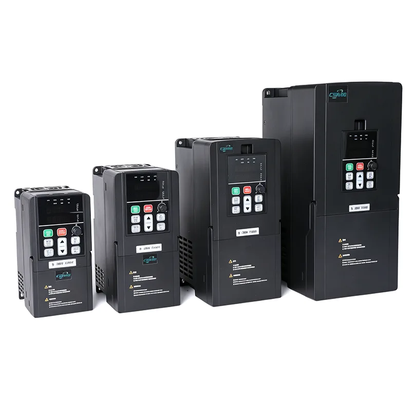
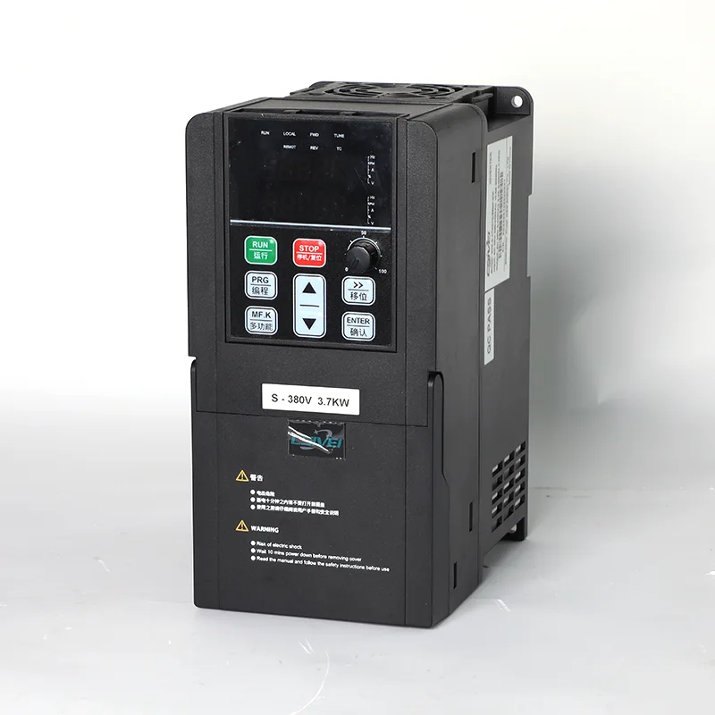
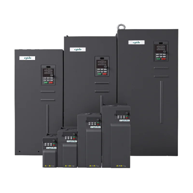
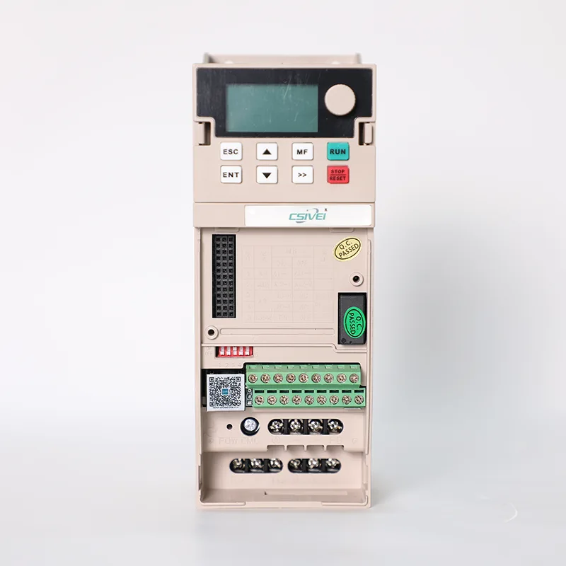
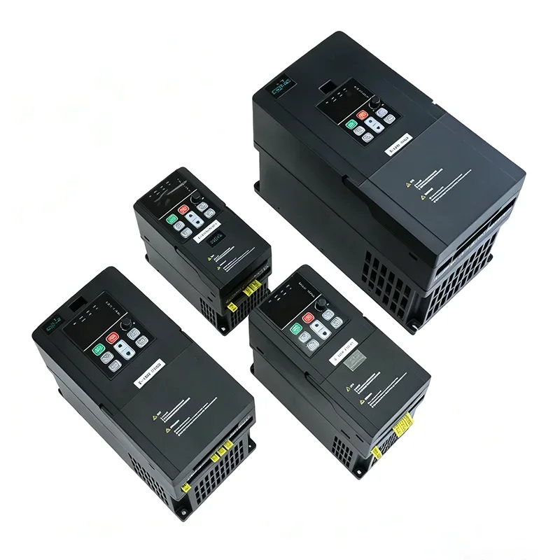
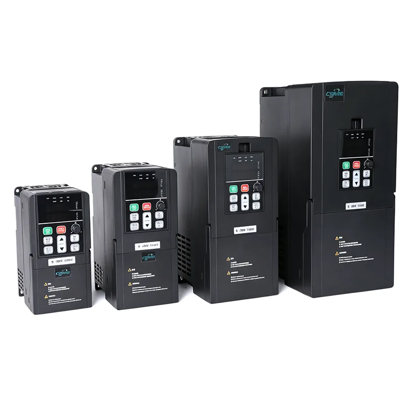
The installed configuration is sixteen 15 kW drives, one per well. The drive selected for this duty is the 15 kW SVD580, model SVD580-4T015G, rated 380 to 480 V three-phase, with an output current of 32 A and an input current of 44 A. The recommended motor cable for this rating is 6 mm² (AWG 8).

One drive per well clears every limit in section 3. Frequency, cable and protection are per well, and a fault stops one well instead of the field.

Each well also carries one RTU. The drives communicate over RS485 Modbus RTU. The control room reads all sixteen wells on one screen, sets speed and start/stop for each well, and receives a fault alarm for each. The same link sets the start order and the delay between wells, so two wells do not come onto the generation at the same moment.

Motor cable length and the output reactor

Long motor cables are the reason an output reactor appears on this type of retrofit. Two rules from the SVD580 manual set the threshold:

● 7.5 to 45 kW models: an output reactor is required when the motor cable reaches 100 m

● 55 to 500 kW models: the same applies from 150 m

When one drive runs several motors, the total cable length is the sum of the individual runs, which puts a field of this size well past the threshold.

The cause sits in the drive output. An IGBT output switches thousands of times a second, and each switching edge travels down the cable. A long cable adds capacitance and reflects the edge at the motor terminals, so the motor sees a steeper voltage rise than the drive itself produces. The reactor limits both the rate of voltage rise and the capacitive current the cable draws. Whether one is required follows the cable run as installed. A shared drive is judged on the summed run of every motor on its output; a per-well drive feeds one motor, so the run is set by the distance from that drive to its motor.

Supply voltage and frequency: 415 V / 50 Hz, not 480 V / 60 Hz

Set the drive to the supply that exists on site. A quotation built around a 60 Hz nameplate does not transfer to a 50 Hz field. On this site the motors and the generation are both 415 V / 50 Hz, and the drives keep that pair: a V/f ratio of 8.3, with full torque available at start.

At 50 Hz these motors run at 933 rpm. At 480 V / 60 Hz the same motors run at about 1120 rpm, roughly 20% higher. On a beam pumping unit that raises the stroke rate and changes the load on the rods and the gearbox, so it is a mechanical decision before it is an electrical one.

The measured supply belongs in the selection as well. This site reads 382 V, about 8% below the 415 V nameplate. NEMA MG 1 allows an induction motor to run within plus or minus 10% of rated voltage, and a supply near the bottom of that band reduces the torque available at rated current. A starting transient on top of a steady 382 V leaves little margin, which is a further reason to hold the motor at its rated V/f point rather than run it above rated speed.

Starting current on diesel generation

Starting current for one jack pump motor reaches six to eight times rated current. On a generator, that surge is drawn from the same source that feeds every other well, so bus voltage dips at each start, and the wells already running see the dip as well.

Two numbers decide how much the dip matters: the generator capacity in kVA, and the number of motors that may start at the same time. Per-well jack pump VFDs limit the surge to one motor's share, and where starts can be staggered the dip stays small. With sixteen motors on one output, any restart adds to the load the drive is already carrying.

Jack pump VFD selection checklist

1. Number of wells, and motor rating per well in kW, with nameplate voltage and full load current

2. Rated speed, and the speed range the pumping unit needs

3. Supply source: grid or diesel generation, with nameplate volts and hertz, plus measured volts and hertz under load

4. Maximum motor cable length from the drive position to each well

5. Whether any well has to keep running while another stops

6. Monitoring and control: protocol, RTU per well, control room screen, fault alarm per well

7. Number of motors that may start simultaneously

8. Environment: enclosure, ambient temperature, dust

Items 5 and 7 decide the architecture, between one shared drive and one drive per well. The remaining items set the model and the bill of materials.

Contact

Csivei | Zhejiang Xiwei Automation Co., Ltd.

No. 3788, Liujiang Road, Liushi Town, Yueqing City, Zhejiang, China

Tel +86 15705777705 | sanchia@csivei.com | csiveivfd.com

Related News
Leave me a message
X
We use cookies to offer you a better browsing experience, analyze site traffic and personalize content. By using this site, you agree to our use of cookies. Privacy Policy
RejectAccept