Whatsapp
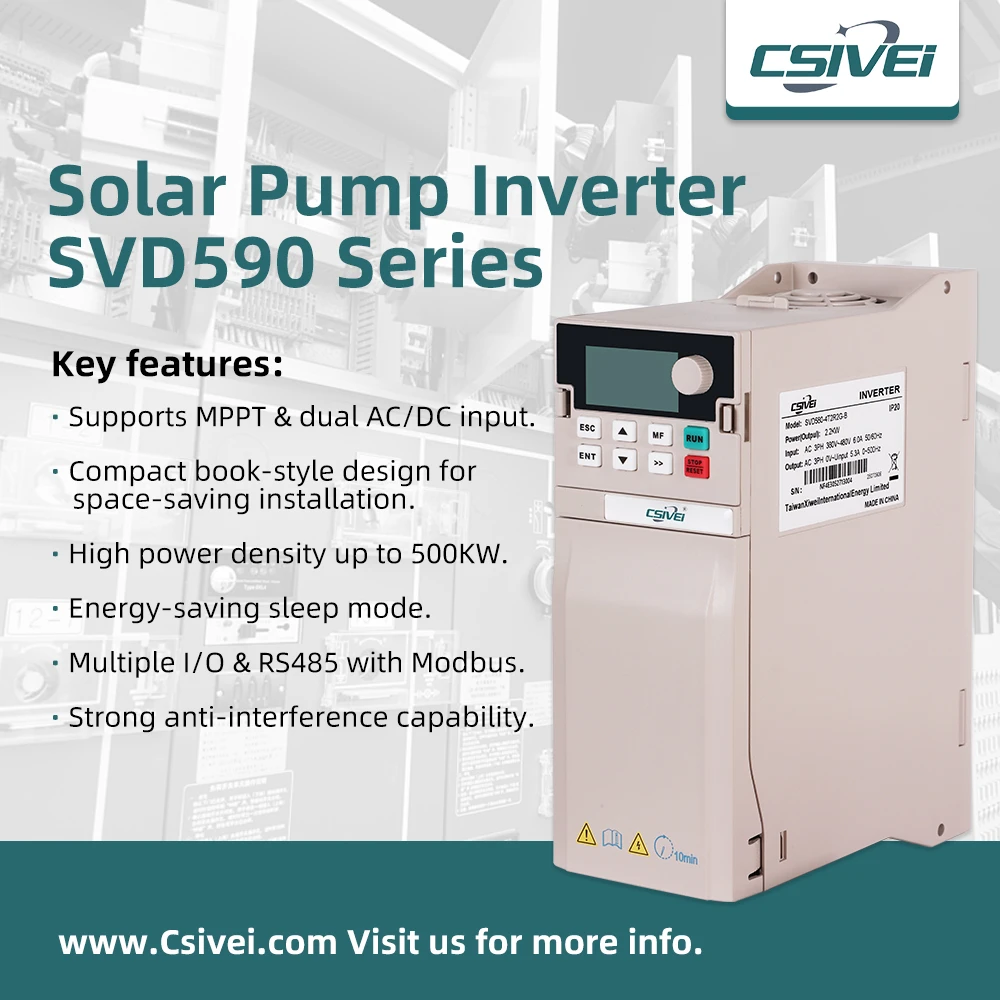
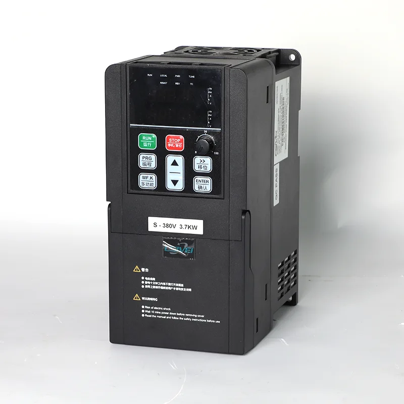
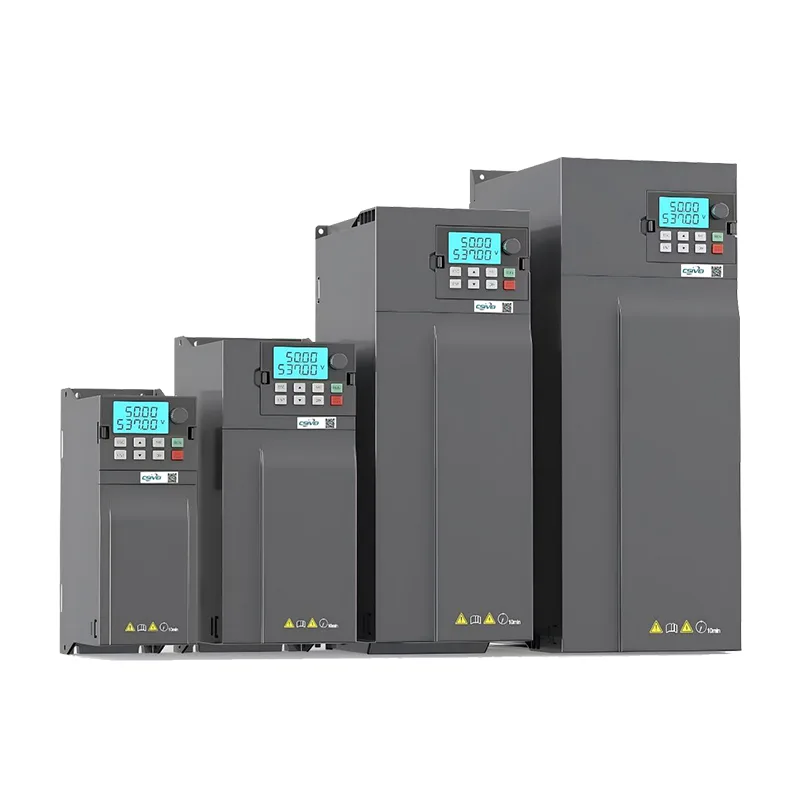
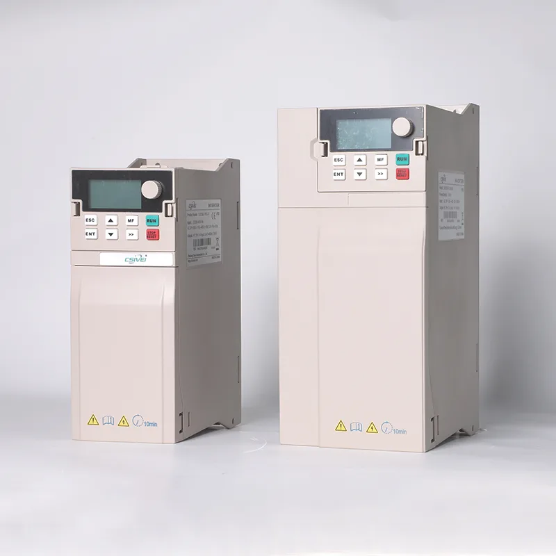
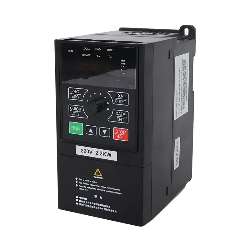
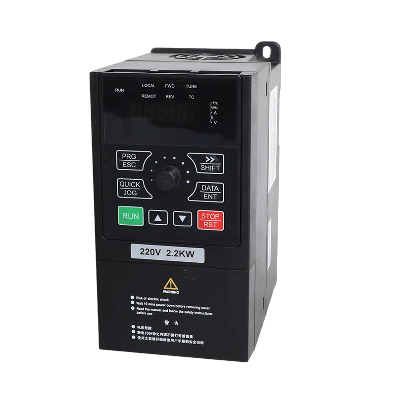
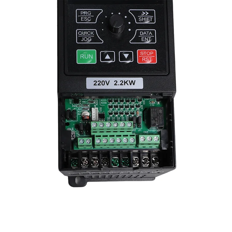
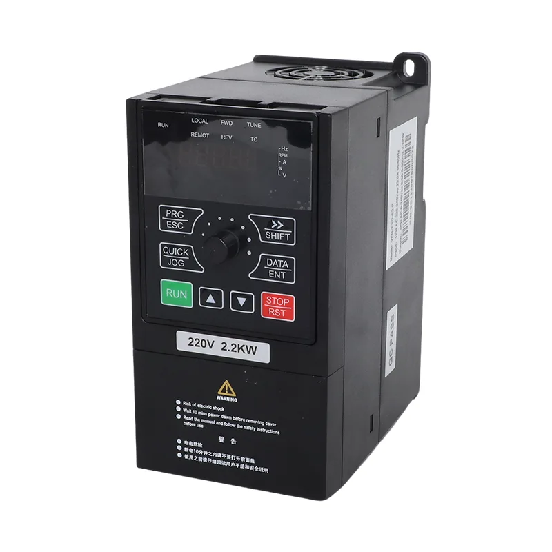
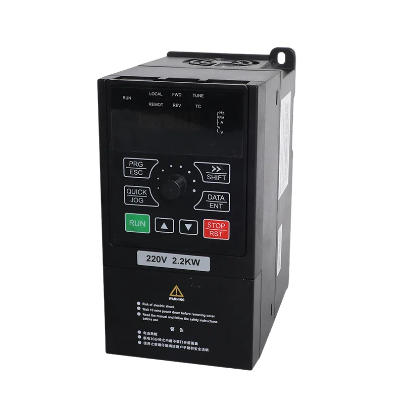
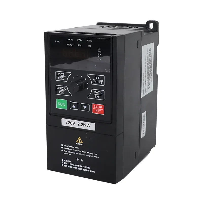
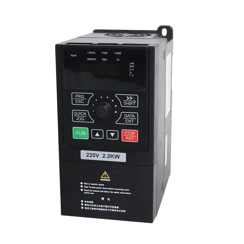
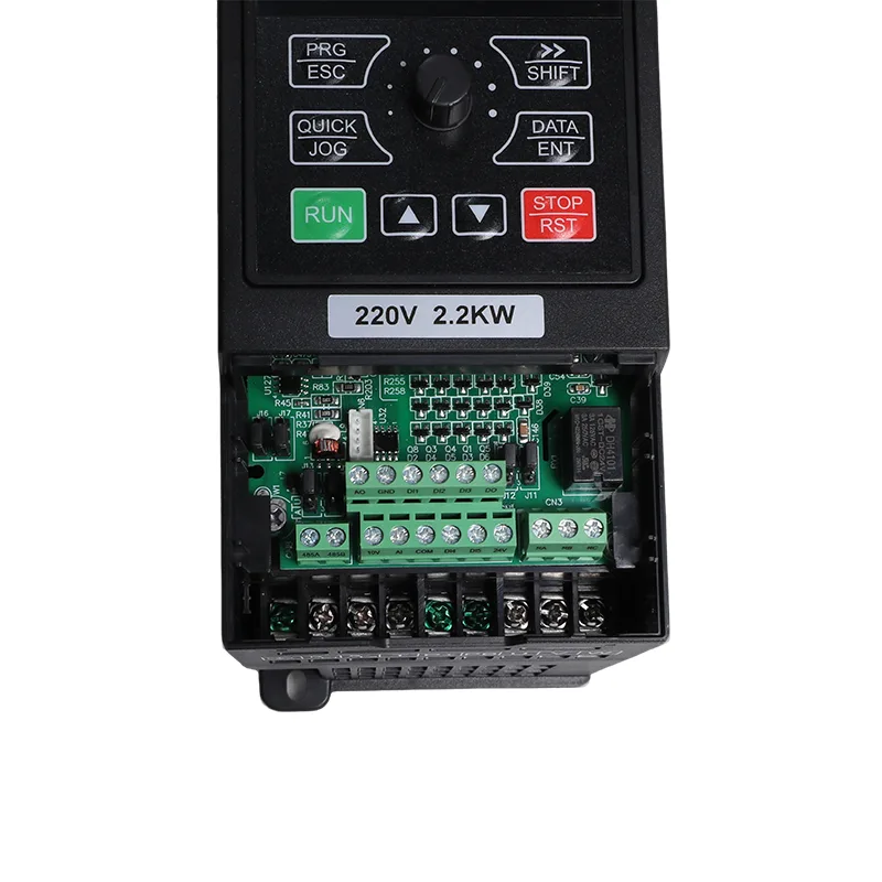
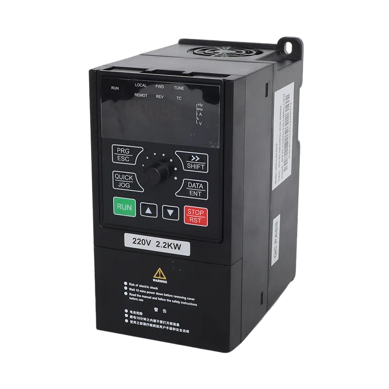
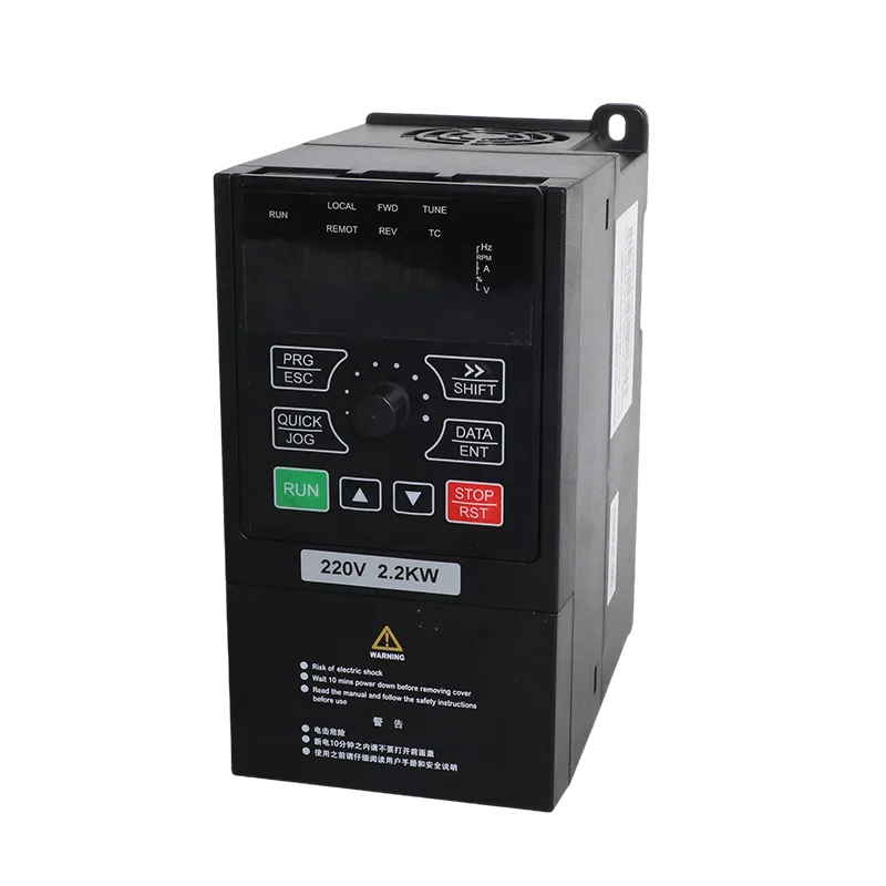
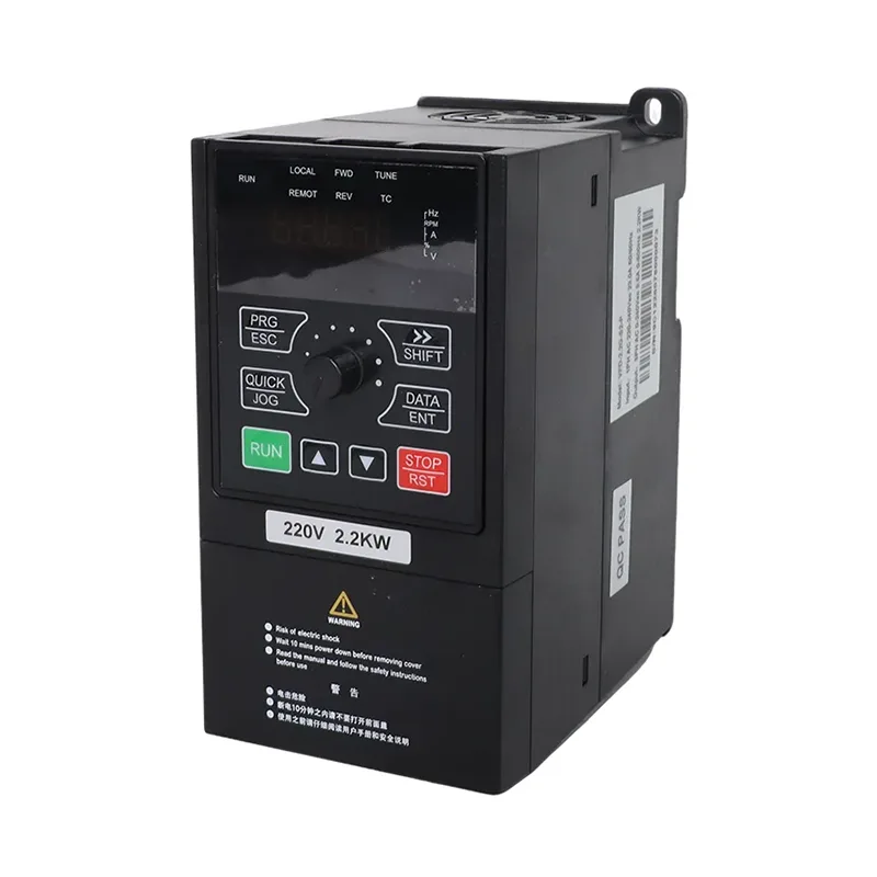
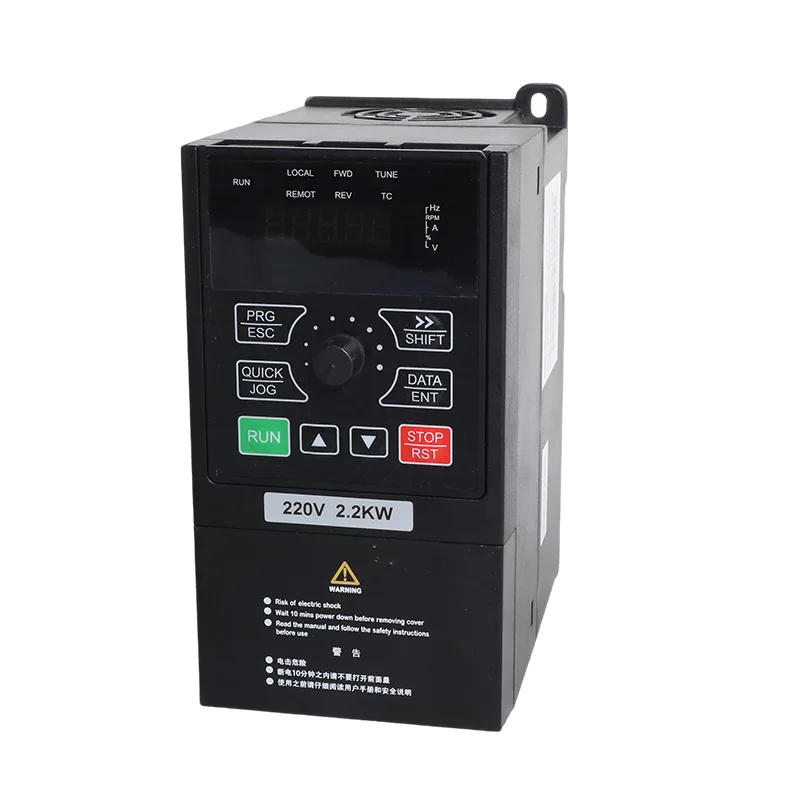
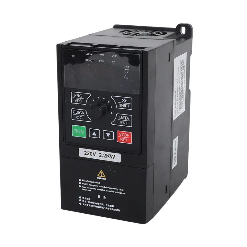
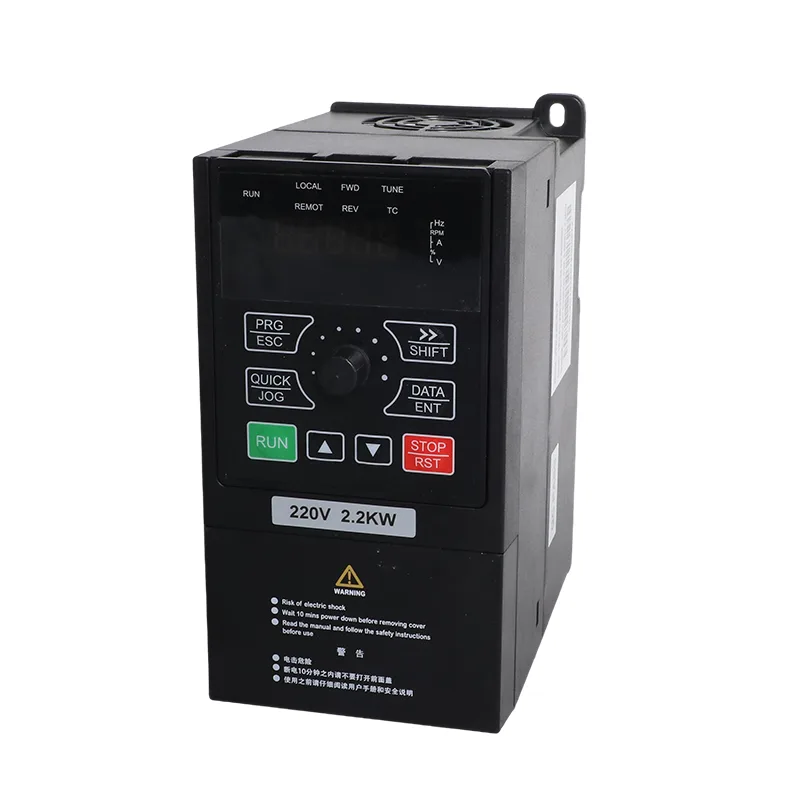
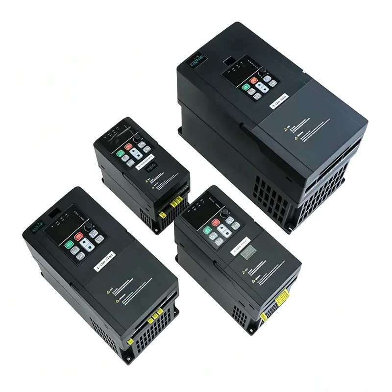
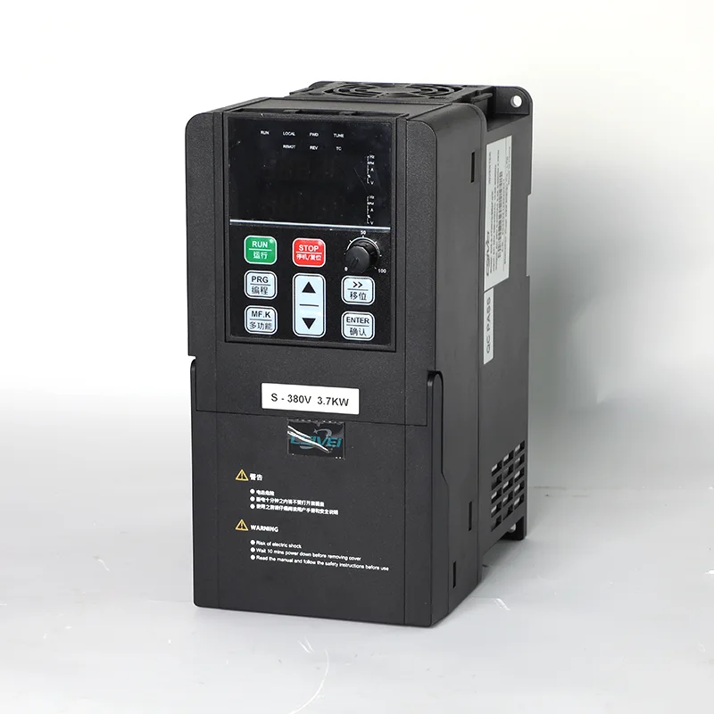
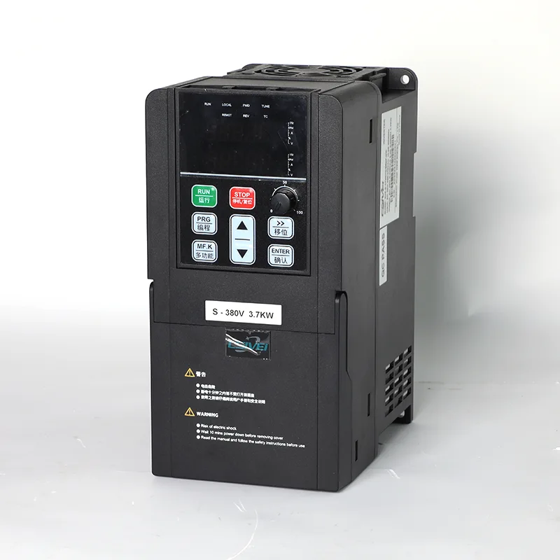
The CSIVEI 4.0kW/5.5kW 1 Phase 230V Solar Pump and General Purpose Inverter VFD is intended for sites that need to operate 4.0 kW or 5.5 kW motors but have a single-phase AC supply rather than a three-phase utility connection. The VFD-PC10-4.0G-S2-MK delivers 17 A output current, while the VFD-PC10-5.5G-S2-MK delivers 25 A. Their listed AC input currents are 32 A and 45 A, respectively, so the supply circuit, breaker and cable must be selected for the actual input current.
On the DC side, the drive accepts a photovoltaic array configured for its voltage limits. The recommended MPPT range is 250–350 VDC, the recommended array open-circuit voltage range is 360–430 VDC, and the maximum DC input voltage is 450 VDC. These limits are especially important when strings are connected in parallel or when the array operates in cold conditions, where module open-circuit voltage can rise.
Solar pump mode (P8-00 = 1): The drive uses MPPT for photovoltaic pumping and provides pump-related functions including weak-light handling, underload protection and water-level control options. When grid backup is part of the installation, the changeover parameters and external switching arrangement must be configured according to the manual.
General-purpose mode (P8-00 = 0): The drive operates as a conventional inverter with SVC or V/F control, built-in PID and RS485 Modbus RTU communication. This mode can be used for compatible pumps, fans, blowers and other motor-driven equipment without using the solar-pump control function.
The operating mode can be set before shipment and changed through P8-00 when application requirements change. This gives distributors and installers a way to specify the intended use while retaining the option to reconfigure the drive later, subject to suitable motor ratings, wiring and parameter settings.
For solar pumping, the 4.0kW/5.5kW 1 Phase 230V Solar Pump and General Purpose Inverter VFD uses a model-specific string layout: the 4.0 kW version uses two parallel strings, while the 5.5 kW version uses three. With 37±1 V, 250 W±5 Wp modules, the table specifies 11 modules per string; with 45±1 V, 300 W±5 Wp modules, it specifies 9 modules per string. Before connecting the array, calculate string open-circuit voltage using the selected module data and local temperature conditions, and keep it within the drive’s stated limits.
For installations that use a storage tank or depend on well-water availability, the drive supports water-level input options and underload protection. AI water-level detection can be configured using P8-18, with the threshold and sleep delay set through P8-19 and P8-20. Underload reset behavior is configured through P8-26. These functions help coordinate pump operation with tank level and water availability when the correct sensors and parameters are installed.


| Item | VFD-PC10-4.0G-S2-MK | VFD-PC10-5.5G-S2-MK |
| Applicable motor | 4.0 kW / 5 HP | 5.5 kW / 7.5 HP |
| Nominal capacity | 5.9 kVA | 11 kVA |
| Input current | 32 A | 45 A |
| Output current | 17 A | 25 A |
| AC input voltage | AC 1 PH 220 V (-15%) to 240 V (+10%) | |
| Max. DC input voltage | 450 VDC | |
| Recommended Voc range | 360 to 430 VDC | |
| Recommended MPPT range | 250 to 350 VDC | |
| Start voltage range | 160 to 450 VDC, parameter adjustable | |
| Rated output voltage | 3 PH or 1 PH 220 V AC | |
| Noise level | 50 dBA max. |
| Model | 37±1 V modules, 250 W±5 Wp | 45±1 V modules, 300 W±5 Wp | ||
| Modules per string | Strings | Modules per string | Strings | |
| VFD-PC10-4.0G-S2-MK | 11 | 2 | 9 | 2 |
| VFD-PC10-5.5G-S2-MK | 11 | 3 | 9 | 3 |
| Item | Specification |
| Rated frequency | 50/60 Hz |
| Input frequency range | ±5% (47.5 to 63 Hz) |
| Output voltage | 0 to input voltage |
| Output frequency | 0.1 to 500 Hz |
| Maximum frequency | 0 to 500 Hz (SVC and V/F control) |
| Carrier frequency | 0.8 kHz to 8 kHz, adjusted automatically to load (up to 16 kHz supported) |
| Frequency resolution | Digital setting 0.01 Hz; analog setting 0.025% of maximum frequency |
| Control mode | Sensorless vector control (SVC); V/F control |
| Starting torque | 0.5 Hz / 150% (SVC) |
| Speed range | 1:100 (SVC) |
| Speed stability accuracy | ±0.5% (SVC) |
| Overload capacity | 150% rated current for 60 s; 170% for 12 s; 190% for 1.5 s |
| Torque boost | Automatic torque boost; manual boost 0.1% to 30.0% |
| V/F curve | Linear, multi-point, and square curve (1.2 / 1.4 / 1.6 / 1.8 / 2.0 power) |
| V/F separation | Full separation, half separation |
| Acceleration / deceleration | Linear or S-curve, 0.0 to 6500.0 s |
| DC braking | Start frequency 0.00 Hz to maximum frequency; time 0.0 to 36.0 s; current 0.0% to 100.0% |
| JOG control | JOG frequency 0.00 Hz to maximum frequency (default 5 Hz); accel/decel 0.0 to 6500.0 s |
| Built-in PID | Yes, for pressure, flow or temperature closed loop without an external controller |
| AVR | Output voltage held stable when grid voltage fluctuates |
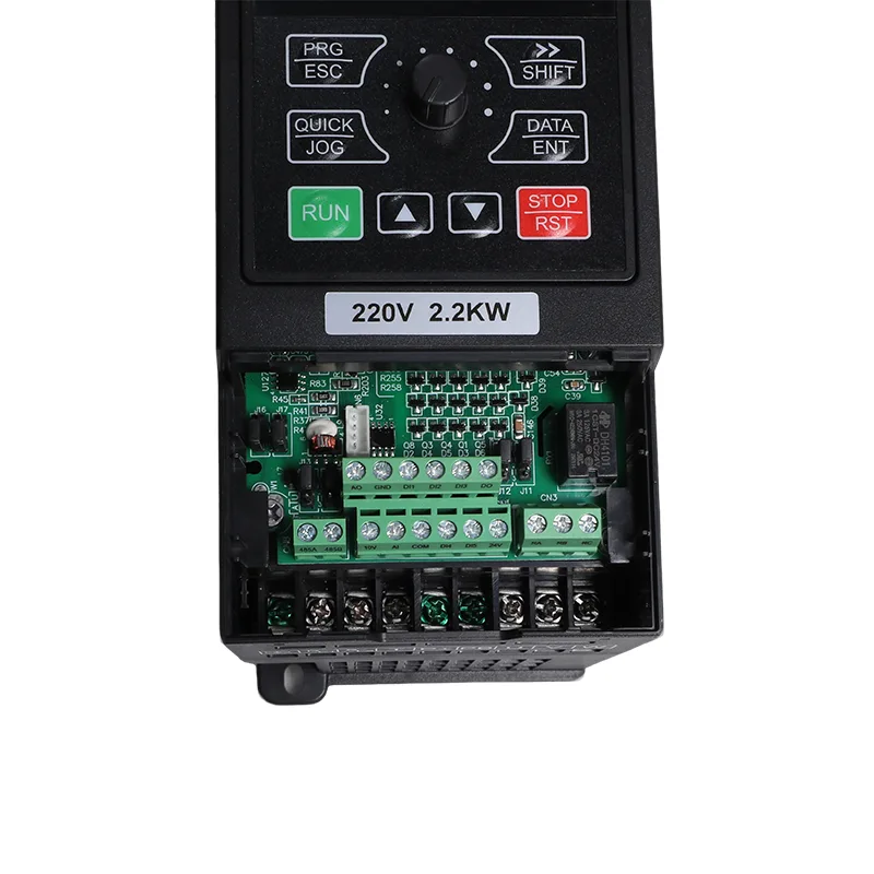
| Input terminals | 5 digital inputs, DI5 supports high-speed pulse up to 50 kHz; 1 analog input 0-10 V or 0-20 mA; 1 keypad potentiometer input |
| Output terminals | 1 high-speed pulse output up to 50 kHz; 1 relay output; 1 analog output 0-20 mA or 0-10 V |
| Communication | RS485, Modbus RTU |
| Protection | Motor short-circuit detection at power-on, output phase loss, over-current, over-voltage, under-voltage, over-temperature, overload, underload, weak light |
| Operating temperature | -10°C to 50°C; derate 1% per 1°C above 40°C |
| Storage temperature | -20°C to 60°C |
| Humidity | Below 95% RH, no condensation |
| Altitude | Below 1000 m; derate 1% per 100 m from 1000 to 3000 m |
| Vibration | Below 5.9 m/s² (0.6 g) |
| Enclosure | IP20, wall mount or cabinet, vertical installation |
| Distribution system | TN, TT |
| EMC / safety | IEC 61800-3 (C3); IEC 61800-5-1 |


4.0 kW and 5.5 kW models provide 17 A and 25 A output current. SVC starting torque is specified at 150% at 0.5 Hz, with overload capacity of 150% rated current for 60 seconds. Their 32 A and 45 A input-current ratings make correct supply, breaker and cable selection essential.
The 4.0 kW model uses two strings and the 5.5 kW model uses three. Keep the array within the recommended 360–430 VDC open-circuit range and the 450 VDC maximum; use a PV breaker and a combiner box for parallel strings.
Underload protection and configurable water-level detection support pump shutdown and restart logic when the appropriate inputs and parameters are set.
P8-00 selects solar pump mode or general-purpose mode. The latter supports SVC/V/F control, built-in PID and RS485 Modbus RTU.
Use a Type II surge protection device when the array is more than 10 m from the drive. The manual recommends an output reactor when the pump cable exceeds 50 m.
The 4.0kW/5.5kW 1 Phase 230V Solar Pump and General Purpose Inverter VFD is intended for installations that need 4.0 kW or 5.5 kW motor capacity but cannot use a three-phase utility supply. Its solar-pump configuration is suited to water applications, while general-purpose mode extends its use to compatible motor-driven equipment.
The 5.5 kW model has a listed input current of 45 A. The supply, breaker and cable must be rated for the installation current and applicable electrical requirements. Solar operation may reduce the amount of energy drawn from the grid when solar power is available, but actual grid use depends on the array, pump load and operating conditions.
The recommended array configuration provides more photovoltaic capacity for the higher-rated 5.5 kW model. Table B lists three parallel strings for the 5.5 kW version and two for the 4.0 kW version. Confirm the array’s total power, string open-circuit voltage and current against the module and inverter specifications.
The PV and grid connections, switching devices and parameter settings must follow the iMaster manual for the selected operating mode. Do not close solar and grid switches simultaneously unless the specified circuit and protection arrangement explicitly permits it. Commissioning and changeover settings, including P8-15, should be applied according to the manufacturer's wiring diagram.
Size the cable according to array current, cable length, installation conditions and applicable electrical requirements. Use cable suitable for outdoor photovoltaic service. The installation guidance specifies a DC breaker on the PV input and a photovoltaic combiner box when strings are connected in parallel.
Underload protection is provided for detecting conditions such as loss of water load. The supplied parameter information lists a 25% detection level, a 60 s confirmation time and a 120 s reset delay. If a level probe is used and fails, the drive can report E43. Verify the configured thresholds and delays against the actual pump and installation.
Yes. P8-00 selects solar pump mode or general-purpose mode. General-purpose mode supports SVC or V/F control, built-in PID and Modbus RTU. CSIVEI can set the requested mode before shipment, and the operating mode can be changed later through the parameter setting when the application and wiring are suitable.
OEM branding and pre-shipment parameter configuration can be discussed when enquiring. Provide the required quantity and label artwork so CSIVEI can confirm the available arrangement, price and schedule.
Address
No. 3788, Liujiang Road, Liushi Town, Yueqing City, Wenzhou City, Zhejiang Province, China
Tel
If you have any enquiry about quotation or cooperation, please feel free to email us at sanchia@csivei.com or use the following inquiry form.Our sales representative will contact you within 24 hours. Thank you for your interest in our products.
WhatsApp:8615705777705