Whatsapp
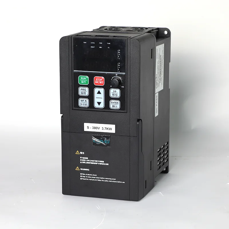
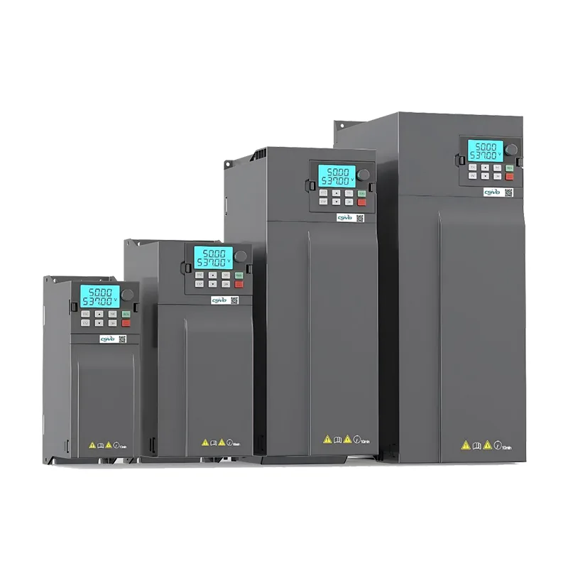
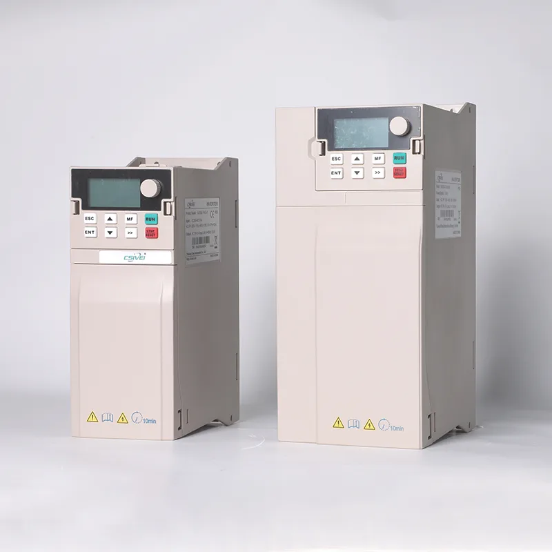
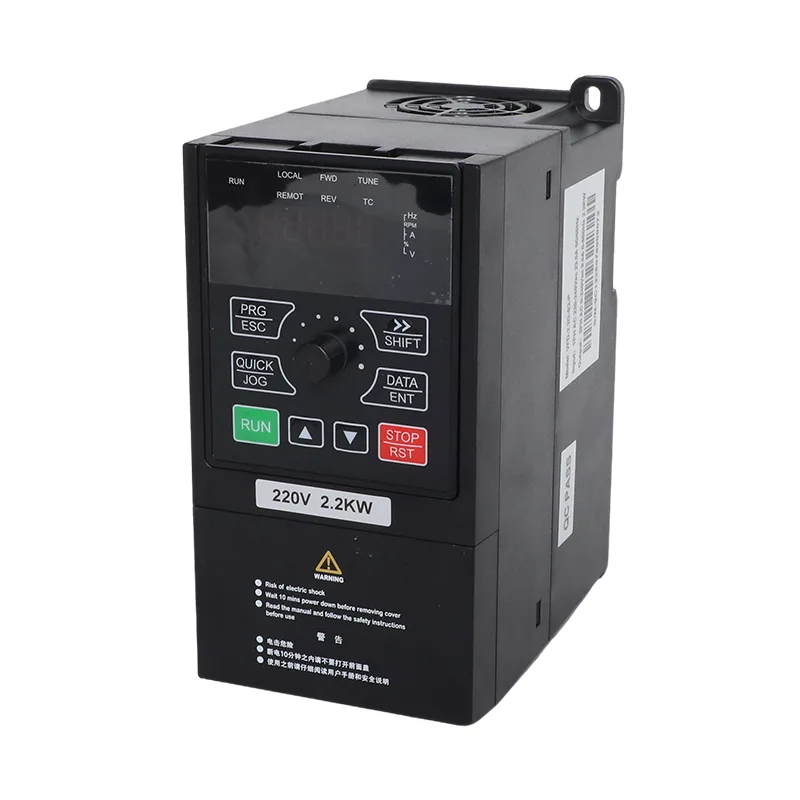
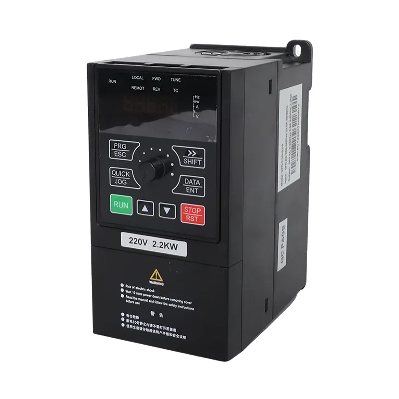
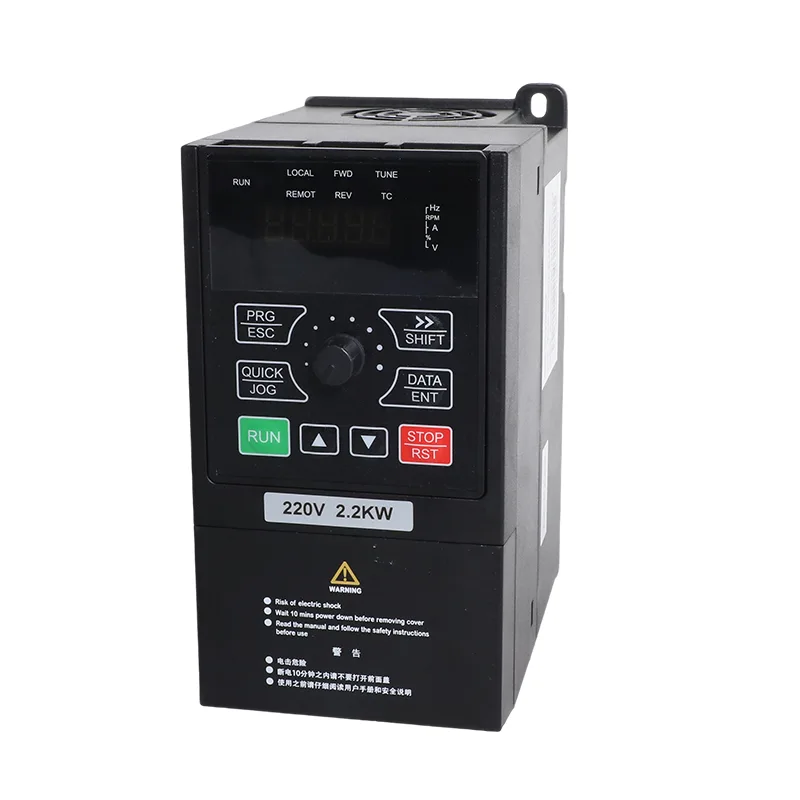
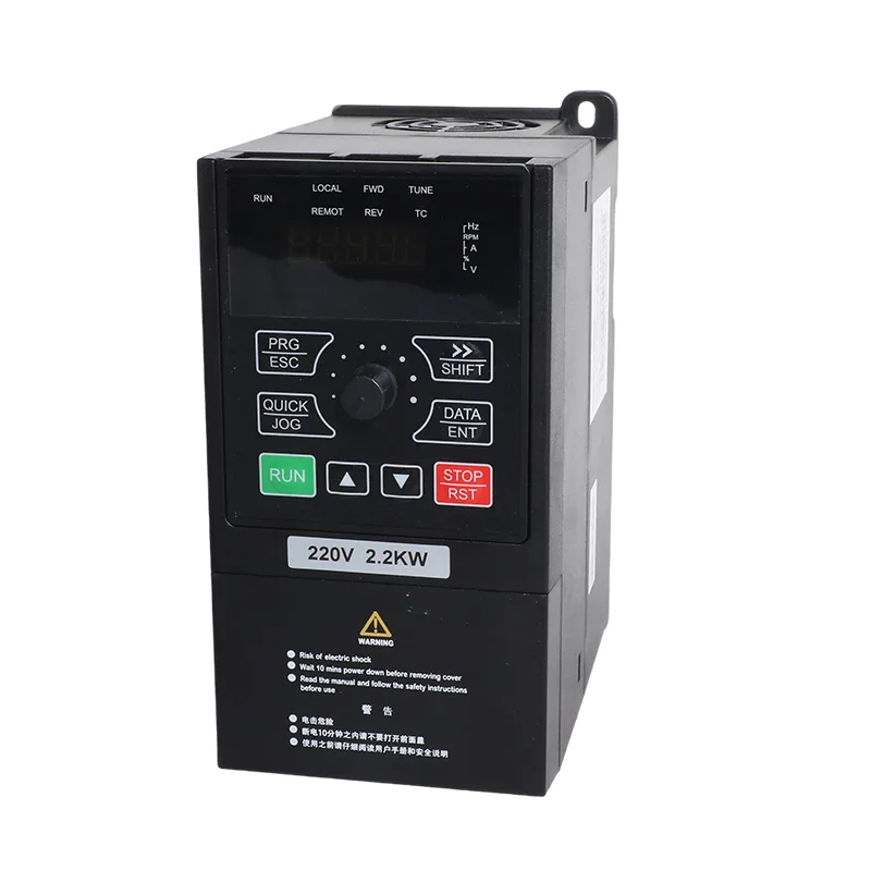
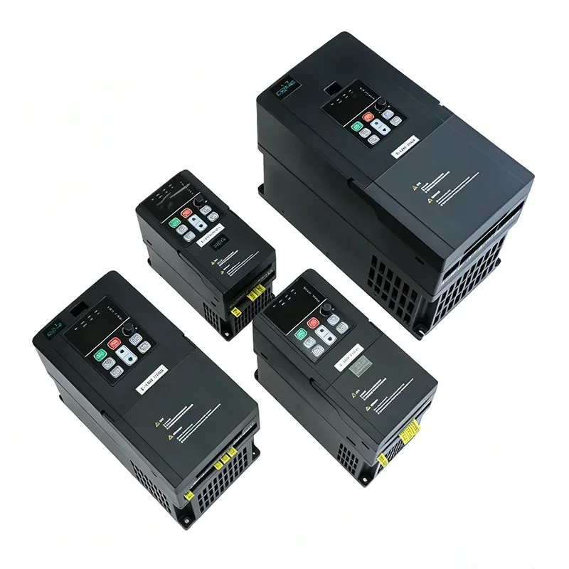
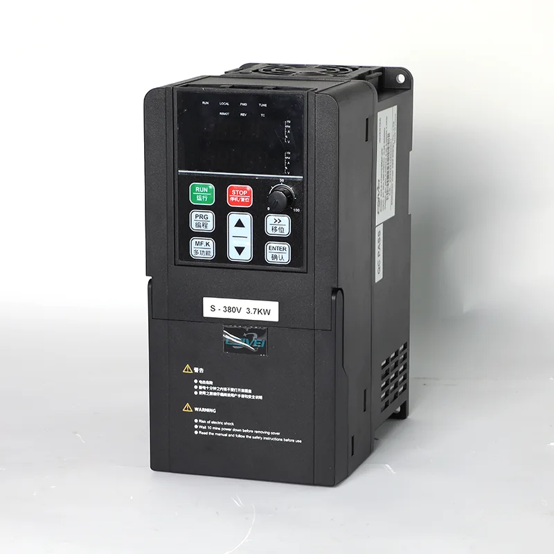
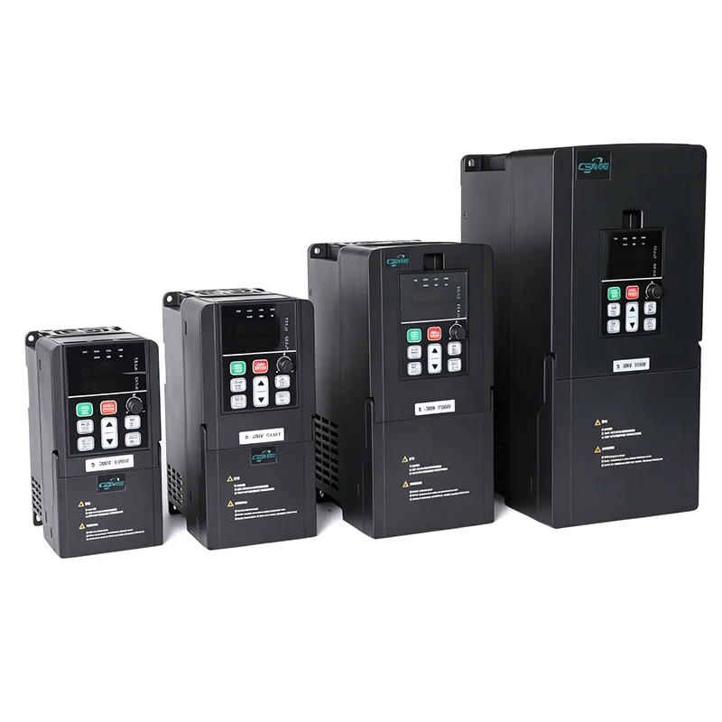
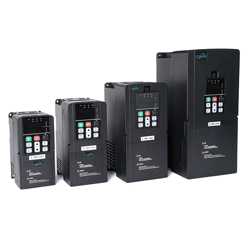
The 30kW/37kW 3 Phase 380V Solar Pump and General Purpose Inverter VFD is available in two models: VFD-PC10-30G-T4-MK and VFD-PC10-37G-T4-MK. Both use a three-phase AC input and support solar pump or general-purpose operation according to the selected configuration.
In solar pump applications, the drive controls the pump motor using power from a photovoltaic array. In general-purpose mode, it provides variable-frequency motor control for compatible industrial equipment. Model selection depends on the motor's rated power and current, the pump operating conditions, the available power source and the required control functions.

For the 30kW/37kW 3 Phase 380V Solar Pump and General Purpose Inverter VFD, operating mode is selected through parameter P8-00 according to the applicable model configuration.
Solar pump mode is intended for pump applications supplied by a photovoltaic array. The control functions listed for this mode include maximum power point tracking (MPPT) and weak-light protection logic.
The PV array must be configured within the drive's specified DC voltage limits. Pump output depends on available solar power, motor requirements, pump characteristics and site conditions.
Where grid or generator backup is required, the input switching arrangement and wiring must follow the applicable model diagram. Confirm whether external switching components are required for the selected installation rather than assuming that all changeover functions are contained within the drive.
General-purpose mode is intended for compatible motor-driven equipment that requires variable-frequency control. The listed functions include SVC and V/F control, built-in PID, adjustable acceleration and deceleration, and Modbus RTU communication.
The operating mode and parameter settings should be established during commissioning. Follow the user manual for the exact model when configuring the control source, motor data, input terminals and operating commands.
| Item | VFD-PC10-30G-T4-MK | VFD-PC10-37G-T4-MK |
| Applicable motor | 30 kW / 40 HP | 37 kW / 50 HP |
| Input current | 57 A | 69 A |
| Output current | 60 A | 75 A |
| AC input voltage | AC 3 PH 380 V (-15%) to 440 V (+10%) | |
| Max. DC input voltage | 900 VDC | |
| Recommended Voc range | 550 to 750 VDC | |
| Recommended MPPT range | 450 to 600 VDC | |
| Start voltage range | 300 to 900 VDC, parameter adjustable | |
| Output frequency range | 0 to 500.00 Hz | |
| Noise level | 65 dBA max. |
| Model | 37±1 V modules, 250 W±5 Wp | 45±1 V modules, 300 W±5 Wp | ||
| Modules per string | Strings | Modules per string | Strings | |
| VFD-PC10-30G-T4-MK | 18 | 8 | 15 | 8 |
| VFD-PC10-37G-T4-MK | 18 | 9 | 15 | 9 |
When planning the PV array, treat the configurations above as reference arrangements rather than universal sizing rules. Confirm the module specifications, pump operating conditions and site requirements before finalizing the array.
PV string design must account for actual open-circuit voltage (Voc), operating voltage, module temperature coefficients and the site's minimum temperature. Verify that the calculated cold-weather string Voc does not exceed the drive's maximum DC input voltage and that the expected operating voltage is compatible with its MPPT range. The final configuration should also account for the pump's motor rating, total dynamic head, daily water demand and site solar conditions.
| Item | Specification |
| Rated frequency | 50/60 Hz |
| Input frequency range | ±5% (47.5 to 63 Hz) |
| Output voltage | 0 to input voltage |
| Output frequency | 0.1 to 500 Hz |
| Maximum frequency | 0 to 500 Hz (SVC and V/F control) |
| Carrier frequency | 0.8 kHz to 8 kHz, adjusted automatically to load (up to 16 kHz supported) |
| Frequency resolution | Digital setting 0.01 Hz; analog setting 0.025% of maximum frequency |
| Control mode | Sensorless vector control (SVC); V/F control |
| Starting torque | 0.5 Hz / 150% (SVC) |
| Speed range | 1:100 (SVC) |
| Speed stability accuracy | ±0.5% (SVC) |
| Overload capacity | 150% rated current for 60 s; 170% for 12 s; 190% for 1.5 s |
| Torque boost | Automatic torque boost; manual boost 0.1% to 30.0% |
| V/F curve | Linear, multi-point, and square curve (1.2 / 1.4 / 1.6 / 1.8 / 2.0 power) |
| V/F separation | Full separation, half separation |
| Acceleration / deceleration | Linear or S-curve, 0.0 to 6500.0 s |
| DC braking | Start frequency 0.00 Hz to maximum frequency; time 0.0 to 36.0 s; current 0.0% to 100.0% |
| JOG control | JOG frequency 0.00 Hz to maximum frequency (default 5 Hz); accel/decel 0.0 to 6500.0 s |
| Built-in PID | Yes, for pressure, flow or temperature closed loop without an external controller |
| AVR | Output voltage held stable when grid voltage fluctuates |
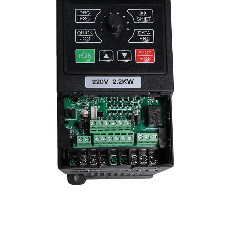
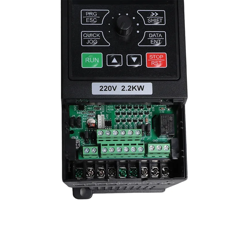
| Input terminals | 5 digital inputs, DI5 supports high-speed pulse up to 50 kHz; 1 analog input 0-10 V or 0-20 mA; 1 keypad potentiometer input |
| Output terminals | 1 high-speed pulse output up to 50 kHz; 1 relay output; 1 analog output 0-20 mA or 0-10 V |
| Communication | RS485, Modbus RTU |
| Protection | Motor short-circuit detection at power-on, output phase loss, over-current, over-voltage, under-voltage, over-temperature, overload, underload, weak light |
| Operating temperature | -10°C to 50°C; derate 1% per 1°C above 40°C |
| Storage temperature | -20°C to 60°C |
| Humidity | Below 95% RH, no condensation |
| Altitude | Below 1000 m; derate 1% per 100 m from 1000 to 3000 m |
| Vibration | Below 5.9 m/s² (0.6 g) |
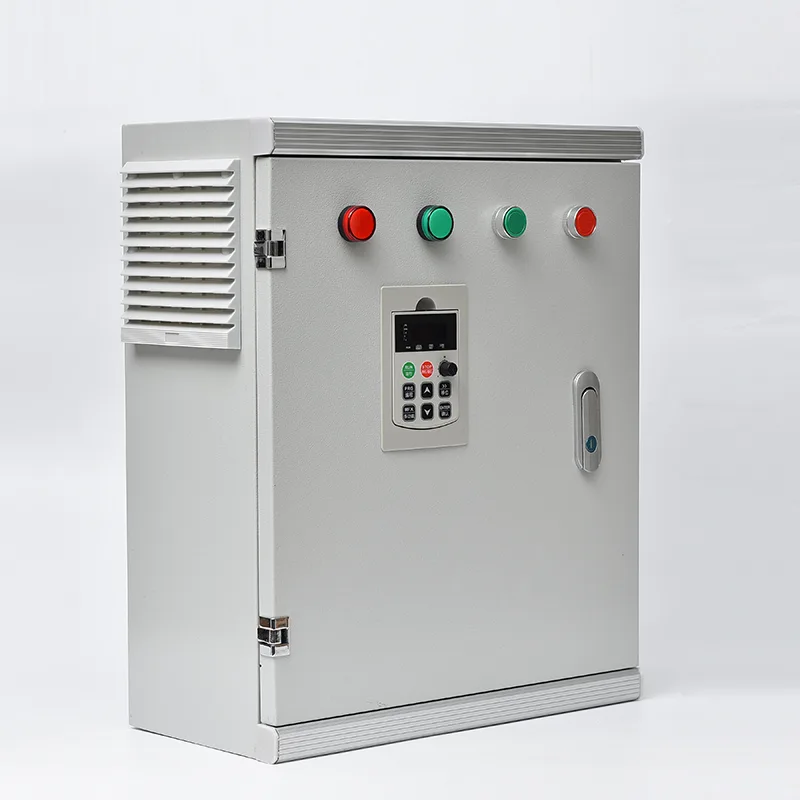
| Enclosure | IP20, wall mount or cabinet, vertical installation |
| Distribution system | TN, TT |
| EMC / safety | IEC 61800-3 (C3); IEC 61800-5-1 |
The drive has a listed maximum DC input voltage of 900 VDC and a recommended MPPT operating range of 450–600 VDC. These values serve different purposes: the maximum input voltage is an upper limit, while the MPPT range relates to normal photovoltaic operation.
The array's open-circuit voltage and operating voltage must be evaluated separately during system design. Do not use the maximum input voltage as the target operating voltage for the PV array.
The listed control methods are sensorless vector control (SVC) and V/F control. Under SVC, the specified starting torque is 150% at 0.5 Hz. The listed speed range is 1:100, with speed stability accuracy of ±0.5%.
Actual motor performance depends on motor parameters, load characteristics, installation conditions and commissioning settings.
The built-in PID function can be used for closed-loop control applications involving pressure, flow or temperature, where the required sensors and system configuration are provided.
Communication is through RS485 using Modbus RTU. The available digital and analog inputs and outputs support the configured control and monitoring functions.
Protection functions do not replace correct motor selection, electrical protection, wiring practices or system commissioning.
The listed overload ratings are:
| Overload level | Duration |
|---|---|
| 150% of rated current | 60 seconds |
| 170% of rated current | 12 seconds |
| 190% of rated current | 1.5 seconds |
These ratings describe the specified short-term overload capacity. They do not by themselves establish suitability for a particular pump's starting requirements. Motor rated current, acceleration time and load characteristics must be checked during selection.


Suitable for evaluating in irrigation pumping systems where the motor rating, pumping duty and available PV array match the drive specifications. Water demand, total head and the site's solar conditions should be considered when configuring the system.
Can be considered for compatible raw-water intake and transfer pumps. Confirm the motor current, required operating frequency, control requirements and any backup-power arrangement before selecting the model.
In general-purpose mode, the drive can be used for compatible industrial pump applications, including process-water transfer, cooling-water circulation and other motor-driven systems requiring variable-frequency control.
For installations with limited or variable grid availability, the drive can be evaluated as part of a solar pumping system with an appropriately designed backup supply. The backup source, changeover arrangement and operating sequence must be confirmed for the specific installation.
Check the motor nameplate, rated current, voltage, power and operating requirements. The drive's rated power alone is not sufficient to establish compatibility with every pump motor.
Confirm the module specifications and calculate string voltage under the site's lowest expected temperature. Ensure that the maximum calculated Voc remains within the drive's DC input limit and that normal operation is compatible with the MPPT range.
If grid or generator operation is required, verify the AC source voltage, frequency, capacity, wiring and changeover components specified for the installation. Do not connect or switch power sources without following the model's wiring diagram.
For motor cables longer than 50 m, check the applicable manual for output-reactor recommendations and permitted cable lengths. Cable length, motor insulation and installation conditions affect the suitability of the output connection.
Account for ambient temperature, altitude, ventilation and enclosure conditions. Derating requirements should be applied when the installation exceeds the specified operating conditions.
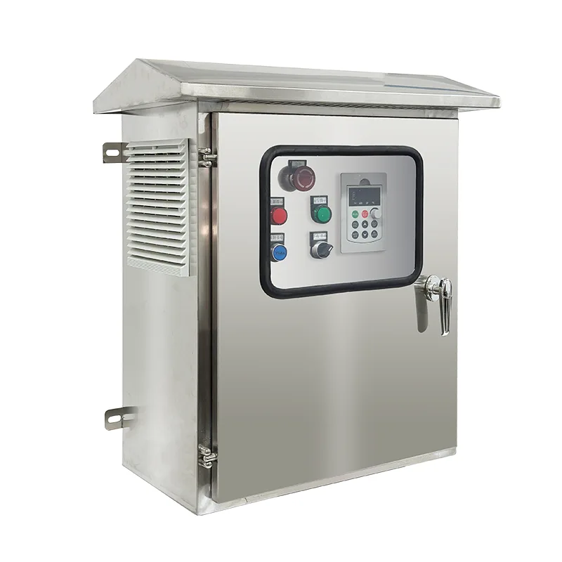
An IP20 enclosure does not provide protection against water ingress. Install the drive in an environment and enclosure suitable for its specified protection rating, temperature and ventilation requirements.
Nine strings of 18 modules at 250 W, or nine strings of 15 at 300 W, which is 162 or 135 modules. Treat that as a starting point and size against daily water volume and total head, because the array determines output, not the motor rating.
Yes. Any 380 V three-phase source on R, S and T works as the backup supply. Set P8-15 to 2 to force mains or generator operation, or to 0 for automatic switching. Confirm generator voltage stability first, since the drive trips on overvoltage or undervoltage like any inverter.
Indoors, out of direct sunlight, no corrosive or flammable gas, no conductive dust. Ambient -10°C to 50°C with derating above 40°C, humidity below 95% RH with no condensation, altitude below 1000 m without derating, vibration below 5.9 m/s². The enclosure is IP20, so a cabinet or a clean pump house is required.
The manual recommends one where the pump is more than 50 m from the drive, which is common at this scale. It protects motor insulation from reflected voltage on long cables and reduces the risk of a winding failure years into the job.
150% of rated current for 60 s, 170% for 12 s and 190% for 1.5 s. On the 37 kW unit that is 112.5 A for a minute, enough for the starting inrush of a large submersible and for transient load spikes.
Yes. Order it in general-purpose mode and P8-00 is set accordingly before it ships, which gives you a standard inverter with SVC or V/F control, PID, Modbus and the full protection set. Solar pump mode is the other option. Tell us which one the project needs. A unit in solar pump mode is switched to general-purpose afterwards with P8-00 at 0, which is a parameter change rather than a return.
Send us the pump rating, total head, daily water volume and the site location, and we will come back with the drive model, the array configuration and the DC protection list as one package. Pricing, lead time and OEM terms are quoted together so you can take the whole thing to your customer in one document.
Address
No. 3788, Liujiang Road, Liushi Town, Yueqing City, Wenzhou City, Zhejiang Province, China
Tel
If you have any enquiry about quotation or cooperation, please feel free to email us at sanchia@csivei.com or use the following inquiry form.Our sales representative will contact you within 24 hours. Thank you for your interest in our products.
WhatsApp:8615705777705