Products
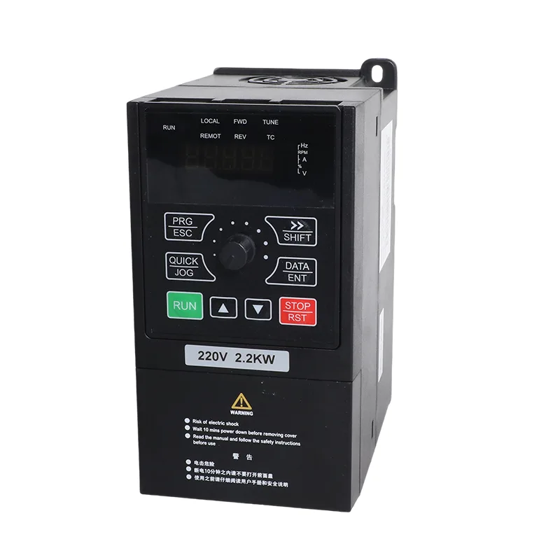
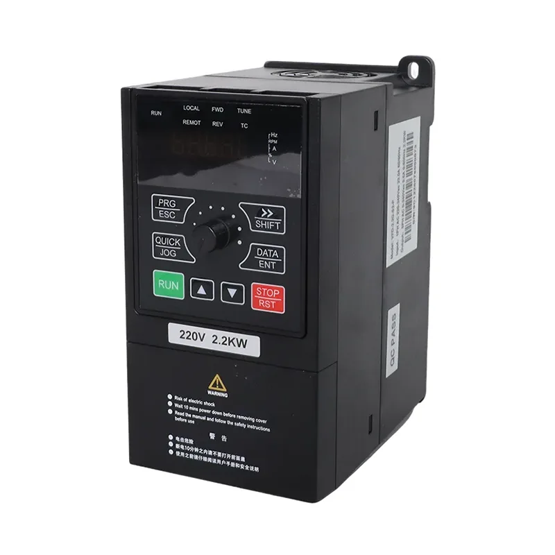
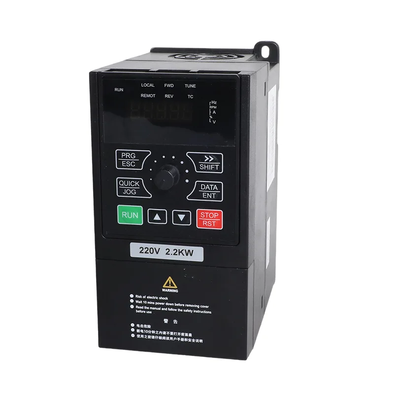
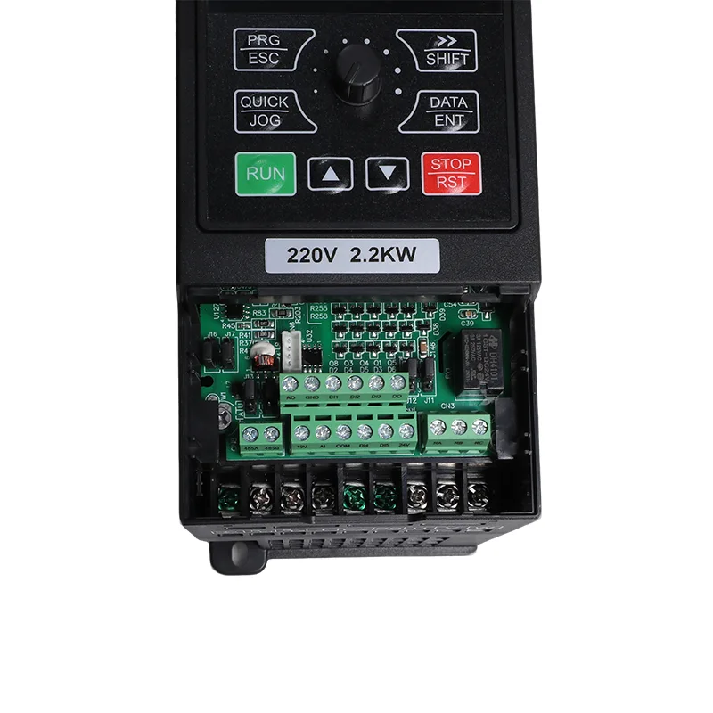
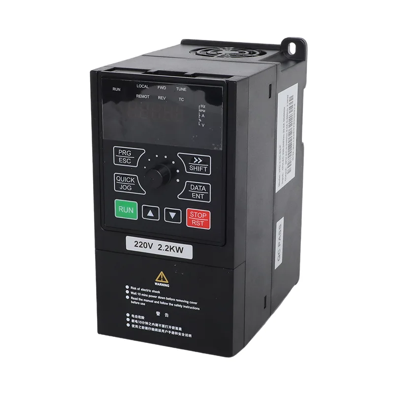
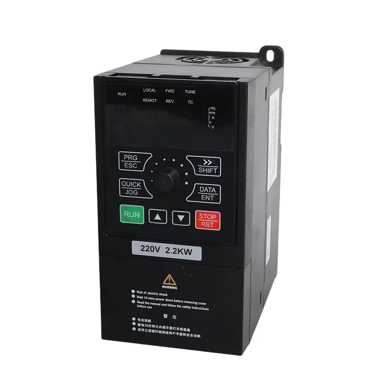
15-22kW 3 Phase 380V Solar Pump and General Purpose Inverter VFD
  • 15-22kW 3 Phase 380V Solar Pump and General Purpose Inverter VFD15-22kW 3 Phase 380V Solar Pump and General Purpose Inverter VFD
  • 15-22kW 3 Phase 380V Solar Pump and General Purpose Inverter VFD15-22kW 3 Phase 380V Solar Pump and General Purpose Inverter VFD
  • 15-22kW 3 Phase 380V Solar Pump and General Purpose Inverter VFD15-22kW 3 Phase 380V Solar Pump and General Purpose Inverter VFD
  • 15-22kW 3 Phase 380V Solar Pump and General Purpose Inverter VFD15-22kW 3 Phase 380V Solar Pump and General Purpose Inverter VFD
  • 15-22kW 3 Phase 380V Solar Pump and General Purpose Inverter VFD15-22kW 3 Phase 380V Solar Pump and General Purpose Inverter VFD

15-22kW 3 Phase 380V Solar Pump and General Purpose Inverter VFD

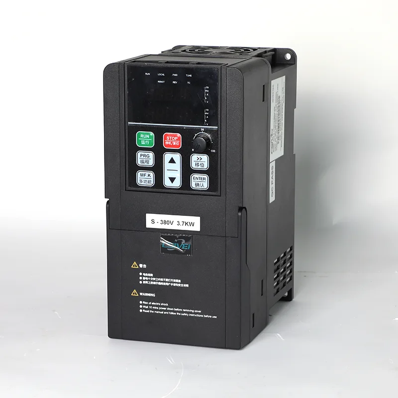
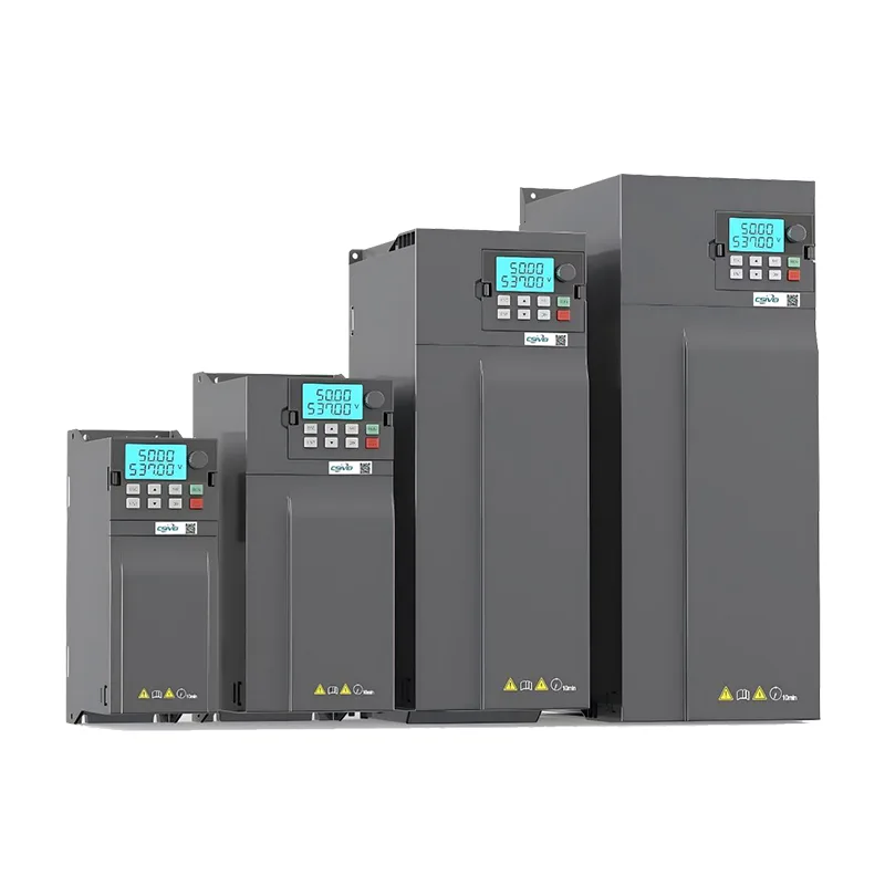
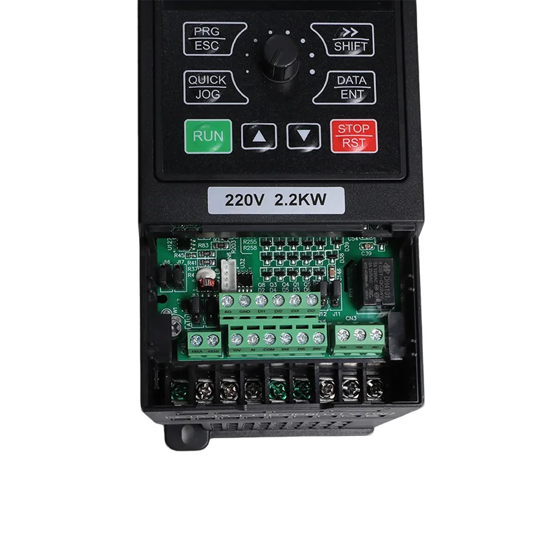
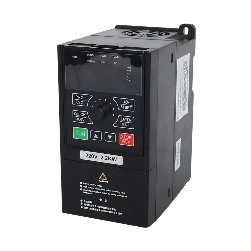
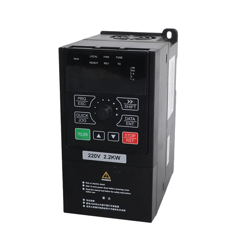
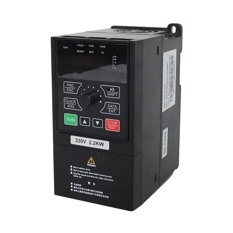
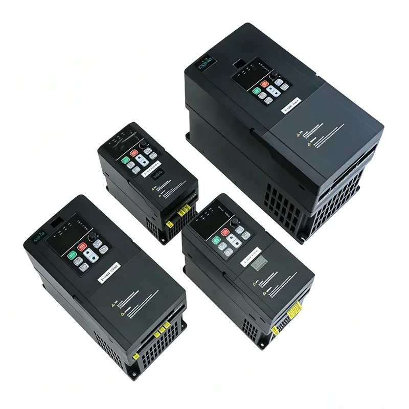
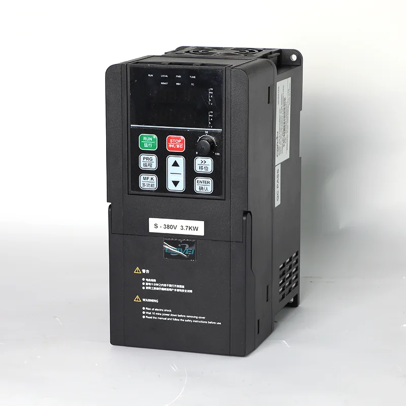
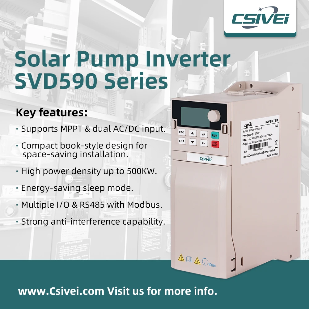
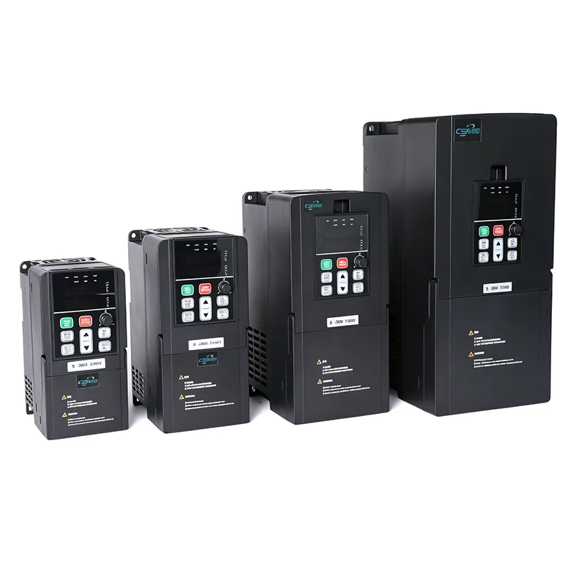
The 15-22kW 3 Phase 380V Solar Pump and General Purpose Inverter VFD covers 15 kW, 18.5 kW and 22 kW models for solar pumping and general-purpose motor control. The series supports MPPT, SVC and V/F control, with external braking resistor terminals P+ and PB listed for this power range. Model selection involves motor current, PV array configuration, braking requirements and the installation's power supply arrangement.

The CSIVEI iMaster VFD-PC10 series includes 15 kW, 18.5 kW and 22 kW three-phase inverter models. The corresponding model numbers are VFD-PC10-15G-T4-MK, VFD-PC10-18.5G-T4-MK and VFD-PC10-22G-T4-MK. Their listed output currents are 32 A, 37 A and 45 A, respectively, for motor applications that meet the drive's electrical requirements.

The 15-22kW 3 Phase 380V Solar Pump and General Purpose Inverter VFD supports two operating configurations: solar pump mode and general-purpose inverter mode. Solar pump mode uses a photovoltaic array as the DC power source and includes MPPT control. General-purpose mode provides variable-frequency motor control using sensorless vector control (SVC) or V/F control.

The main circuit diagrams supplied for this power range identify P+ and PB terminals for connecting an external braking resistor. This connection is relevant when the application requires a braking resistor for controlled deceleration. Resistor selection, wiring and operating limits must follow the applicable model's technical documentation.

15-22kW 3 Phase 380V Solar Pump and General Purpose Inverter VFD15-22kW 3 Phase 380V Solar Pump and General Purpose Inverter VFD15-22kW 3 Phase 380V Solar Pump and General Purpose Inverter VFD

Model Specifications

Item VFD-PC10-15G-T4-MK VFD-PC10-18.5G-T4-MK VFD-PC10-22G-T4-MK
Applicable motor 15 kW / 20 HP 18.5 kW / 25 HP 22 kW / 30 HP
Nominal capacity 37 kVA 44 kVA 60 kVA
Input current 37.9 A 46.7 A 55.6 A
Output current 32 A 37 A 45 A
AC input voltage AC 3 PH 380 V (-15%) to 440 V (+10%)
Max. DC input voltage 900 VDC
Recommended Voc range 550 to 750 VDC
Recommended MPPT range 450 to 600 VDC
Start voltage range 300 to 900 VDC, parameter adjustable
Braking resistor terminals P+ and PB, external resistor
Noise level 65 dBA max.

Check the motor nameplate and the inverter's rated output current before selecting a model. The drive's kW rating alone does not establish suitability for every motor or pump duty. Confirm the applicable electrical limits against the documentation for the exact model.

Table B. Recommended Solar Array Configuration

The supplied configuration table lists different module quantities for the 15 kW, 18.5 kW and 22 kW models. These arrangements should be treated as reference configurations and checked against the PV module datasheet and site conditions before installation.

Model 37±1 V modules, 250 W±5 Wp 45±1 V modules, 300 W±5 Wp
Modules per string Strings Modules per string Strings
VFD-PC10-15G-T4-MK 18 4 15 4
VFD-PC10-18.5G-T4-MK 18 5 15 5
VFD-PC10-22G-T4-MK 18 6 15 6

The nominal PV array power above is calculated from the stated module wattage and quantity. It is not a substitute for a complete PV system design.

PV String Voltage

The listed maximum DC input voltage is 900 VDC. The recommended open-circuit voltage range is 550–750 VDC, and the recommended MPPT operating range is 450–600 VDC. These values describe different operating limits and should not be used interchangeably.

Before finalizing a string arrangement, calculate the expected open-circuit voltage using the selected module's Voc and temperature coefficient. The calculation must account for the site's minimum expected temperature. Verify that the calculated cold-weather string voltage remains within the inverter's maximum DC input limit and that normal operating voltage is suitable for the specified MPPT range.

DC-Side System Design

PV strings, DC cabling, isolators, overcurrent protection, surge protection and combiner equipment should be considered as part of the overall installation. The required devices and their ratings depend on the array configuration, wiring arrangement, cable route and applicable electrical requirements.

For parallel strings, confirm the required combiner and string protection arrangement with the inverter installation manual and the PV system designer. Surge protection requirements should also be determined from the installation layout and applicable instructions. Do not select DC protective devices solely from the inverter's rated power.

Table C. General specifications (same across the iMaster range)

Item Specification
Rated frequency 50/60 Hz
Input frequency range ±5% (47.5 to 63 Hz)
Output voltage 0 to input voltage
Output frequency 0.1 to 500 Hz
Maximum frequency 0 to 500 Hz (SVC and V/F control)
Carrier frequency 0.8 kHz to 8 kHz, adjusted automatically to load (up to 16 kHz supported)
Frequency resolution Digital setting 0.01 Hz; analog setting 0.025% of maximum frequency
Control mode Sensorless vector control (SVC); V/F control
Starting torque 0.5 Hz / 150% (SVC)
Speed range 1:100 (SVC)
Speed stability accuracy ±0.5% (SVC)
Overload capacity 150% rated current for 60 s; 170% for 12 s; 190% for 1.5 s
Torque boost Automatic torque boost; manual boost 0.1% to 30.0%
V/F curve Linear, multi-point, and square curve (1.2 / 1.4 / 1.6 / 1.8 / 2.0 power)
V/F separation Full separation, half separation
Acceleration / deceleration Linear or S-curve, 0.0 to 6500.0 s
DC braking Start frequency 0.00 Hz to maximum frequency; time 0.0 to 36.0 s; current 0.0% to 100.0%
JOG control JOG frequency 0.00 Hz to maximum frequency (default 5 Hz); accel/decel 0.0 to 6500.0 s
Built-in PID Yes, for pressure, flow or temperature closed loop without an external controller
AVR Output voltage held stable when grid voltage fluctuates
Input terminals 5 digital inputs, DI5 supports high-speed pulse up to 50 kHz; 1 analog input 0-10 V or 0-20 mA; 1 keypad potentiometer input
Output terminals 1 high-speed pulse output up to 50 kHz; 1 relay output; 1 analog output 0-20 mA or 0-10 V
Communication RS485, Modbus RTU
Protection Motor short-circuit detection at power-on, output phase loss, over-current, over-voltage, under-voltage, over-temperature, overload, underload, weak light
Operating temperature -10°C to 50°C; derate 1% per 1°C above 40°C
Storage temperature -20°C to 60°C
Humidity Below 95% RH, no condensation
Altitude Below 1000 m; derate 1% per 100 m from 1000 to 3000 m
Vibration Below 5.9 m/s² (0.6 g)
Enclosure IP20, wall mount or cabinet, vertical installation
Distribution system TN, TT
EMC / safety IEC 61800-3 (C3); IEC 61800-5-1

Operating Modes

1. Solar Pump Mode

Solar pump mode is intended for pump applications powered by a photovoltaic array. The listed control functions include maximum power point tracking (MPPT) and weak-light protection logic.

The amount of power available to the pump depends on solar irradiance, the PV array configuration, the motor requirements, pump characteristics and site conditions. The array must therefore be designed around the inverter's voltage limits as well as the required water delivery duty.

Where grid or generator backup is required, confirm the input switching arrangement and wiring against the applicable model diagram. External switching components may be required depending on the configured system; do not assume all source-changeover functions are contained within the inverter.

2. General-Purpose Inverter Mode

General-purpose mode provides variable-frequency control for compatible motor-driven equipment. The listed functions include SVC and V/F control, PID, adjustable acceleration and deceleration, and RS485 Modbus RTU communication.

The operating mode is selected through parameter P8-00 according to the supplied configuration. The correct mode and control parameters should be confirmed during commissioning, using the instructions for the specific model and firmware version.

Technical Features

1. External Braking Resistor Connection

The main circuit diagrams for the 15 kW, 18.5 kW and 22 kW models identify P+ and PB terminals for an external braking resistor. This connection can be relevant when an application requires controlled deceleration rather than allowing the motor to coast to a stop.

The need for a braking resistor depends on the load inertia, deceleration requirements and operating duty. Confirm resistor specifications, wiring requirements and permissible braking conditions in the applicable manual before installation.

2. Overload Capacity

The supplied general specifications list the following short-term overload ratings:

Overload level Duration
150% of rated current 60 seconds
170% of rated current 12 seconds
190% of rated current 1.5 seconds

These ratings describe the listed overload capacity. They do not, on their own, guarantee that a particular motor can start successfully. Selection should account for motor rated current, pump load, acceleration time and the intended starting sequence.

3. Motor Control and PID

The listed control modes are sensorless vector control (SVC) and V/F control. Under SVC, the general specification lists a starting torque of 150% at 0.5 Hz, a speed range of 1:100 and speed stability accuracy of ±0.5%.

The built-in PID function is listed for closed-loop control of variables such as pressure, flow and temperature. The required sensors, feedback signals and control sequence must be configured for the actual application.

4. Protection Functions

The listed protection functions include:

  • Motor short-circuit detection at power-on
  • Output phase-loss protection
  • Overcurrent protection
  • Overvoltage and undervoltage protection
  • Overtemperature protection
  • Overload and underload protection
  • Weak-light protection

The supplied source also lists alarms associated with weak solar input, a full tank, lack of water and motor underload. Alarm codes and meanings should be checked against the exact model's manual before being used for installation or troubleshooting.

5. Control Platform and Communication

The supplied product information states that the 15 kW, 18.5 kW and 22 kW models use the same control platform, with consistent terminal layout, parameter numbering and keypad operation across the three ratings. Confirm the applicable wiring and parameter details for the supplied model before commissioning.

RS485 communication with Modbus RTU is listed as standard for the series. The available monitoring values and control registers should be verified in the communication register map for the applicable version.

Typical Applications

1. Agricultural Irrigation

The drive can be evaluated for irrigation pumps supplying canal networks, large irrigation zones or other agricultural water systems. Motor current, required water flow, total dynamic head, PV array configuration and daily operating requirements should be checked before selecting the model.

2. Municipal Water Supply

For raw-water intake, transfer to treatment facilities or supply to distribution reservoirs, selection should account for pump duty, motor data, control requirements and the availability of the intended power source.

3. Mine Dewatering

In mine and pit-water applications, confirm the pump motor rating, expected load variation, required operating duration and installation conditions. The inverter must be matched to the actual motor and site requirements.

4. Aquaculture Water Exchange

For fish and shrimp farms with regular water-exchange requirements, the drive can be considered for compatible pumping equipment. The system design should account for the required water volume, pumping schedule and available solar or AC power.

5. Industrial Water Transfer and Cooling

In general-purpose mode, the drive can be evaluated for compatible industrial water-transfer, cooling-circuit and process-water applications requiring variable-frequency motor control.

6. Fans, Blowers and Other Process Drives

The general-purpose configuration can be considered for compatible fans, blowers and other motor-driven equipment. Confirm the load characteristics, motor data, deceleration requirements and any need for an external braking resistor before selecting the model.

Installation and Selection Considerations

1. Match the Drive to the Motor

Check the motor nameplate for rated power, current, voltage and frequency. Compare the motor's rated current with the selected model's output current and evaluate the load and acceleration requirements before confirming the inverter rating.

2. Confirm the Need for a Braking Resistor

Where controlled deceleration is required, evaluate whether an external braking resistor is appropriate for the application. Verify the resistor rating, terminal arrangement, wiring and braking limits against the model-specific documentation.

3. Review Output Cable Length

The supplied source identifies an output reactor recommendation for pump installations where the drive-to-motor cable exceeds 50 m. Check the relevant manual for the applicable cable-length guidance, reactor requirements and installation conditions. Consider the motor insulation and cable arrangement when evaluating the output connection.

4. Verify PV Protection and Wiring

Check the array design, parallel-string arrangement, DC isolator, overcurrent protection, combiner equipment and surge protection requirements. The appropriate devices and ratings should follow the inverter manual, PV design and applicable electrical standards.

5. Account for Temperature and Altitude

The listed operating temperature is -10°C to 50°C, with a derating requirement of 1% per 1°C above 40°C. The listed altitude guidance requires derating of 1% per 100 m from 1000 m to 3000 m. Confirm the applicable installation requirements for the actual model, including any additional requirements at higher altitudes.

6. Follow the Commissioning Procedure

Configure the motor data, command source, control mode and acceleration or deceleration settings according to the model's instructions. The supplied FAQ identifies parameters F3-00 to F3-04 for motor data and recommends auto-tuning before first operation. Follow the actual model's manual for the complete commissioning procedure.

Frequently Asked Questions

1. Why do the 15 kW to 22 kW models have braking resistor terminals?

The supplied main circuit diagram identifies P+ and PB terminals for connecting an external braking resistor on the 15 kW, 18.5 kW and 22 kW models. Whether a resistor is required depends on the load, inertia and deceleration requirements. For other power ratings, verify the terminal layout and braking-resistor provisions before ordering.

2. Can the 22 kW model start a 22 kW submersible pump?

Suitability must be evaluated using the motor's rated current, starting requirements, pump load and acceleration settings. The listed SVC starting torque is 150% at 0.5 Hz, and the series overload rating is 150% of rated current for 60 seconds. These figures do not guarantee compatibility with every 22 kW submersible pump. Configure the motor nameplate data and follow the applicable auto-tuning and commissioning instructions.

3. What DC protection is required for a six-string PV array?

The supplied installation information calls for a DC-rated breaker at the PV input, a PV combiner box where parallel strings are combined, and a Type II surge protection device for the specified array-distance condition. Confirm the exact device ratings, placement and cable-distance requirements against the installation manual and the PV system design before commissioning.

4. How does derating affect a 22 kW installation?

The listed temperature derating is 1% for every 1°C above 40°C, with an operating temperature range of -10°C to 50°C. The listed altitude derating is 1% per 100 m from 1000 m to 3000 m. The supplied source also identifies an isolation-transformer requirement above 2000 m; verify this requirement and its conditions in the exact model's manual before installation.

5. What monitoring functions are available through Modbus?

RS485 Modbus RTU is listed as the communication interface. The supplied source identifies the U0 monitoring group as including output current, output power, bus voltage, digital input and output status, and supply mode at U0-49. Confirm the register map and available data for the supplied firmware version before integration.

6. Can these models operate as general-purpose inverters rather than solar pump drives?

The supplied product information identifies solar pump mode and general-purpose mode as configuration options. General-purpose functions include SVC or V/F control, PID and Modbus RTU, while the 15 kW to 22 kW models also have P+ and PB terminals identified for an external braking resistor. Parameter P8-00 is specified as the mode-selection parameter in the supplied material. Confirm the correct setting and permitted conversion procedure in the model-specific manual.

7. Do the 15 kW, 18.5 kW and 22 kW models share the same control platform?

The supplied product information states that the three ratings share a control platform, including consistent parameter numbering, keypad operation and terminal-layout conventions. The rated current and power differ by model, so selection and wiring must still follow the specifications and diagrams for the exact unit.

Send Inquiry
Contact Info

If you have any enquiry about quotation or cooperation, please feel free to email us at sanchia@csivei.com or use the following inquiry form.Our sales representative will contact you within 24 hours. Thank you for your interest in our products.


WhatsApp:8615705777705

Web:www.csiveivfd.com


X
We use cookies to offer you a better browsing experience, analyze site traffic and personalize content. By using this site, you agree to our use of cookies. Privacy Policy
RejectAccept