Whatsapp
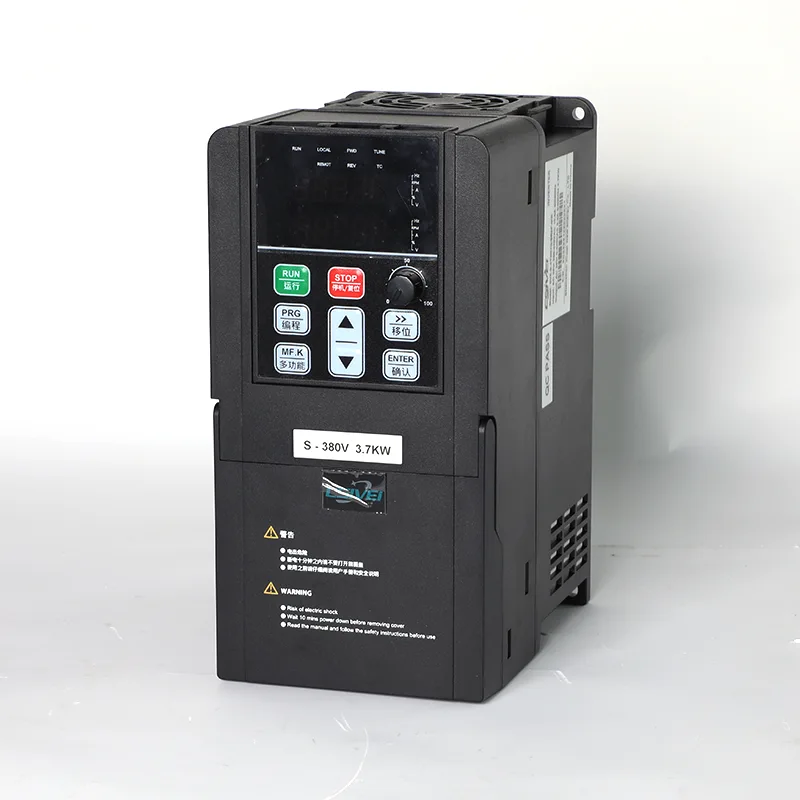
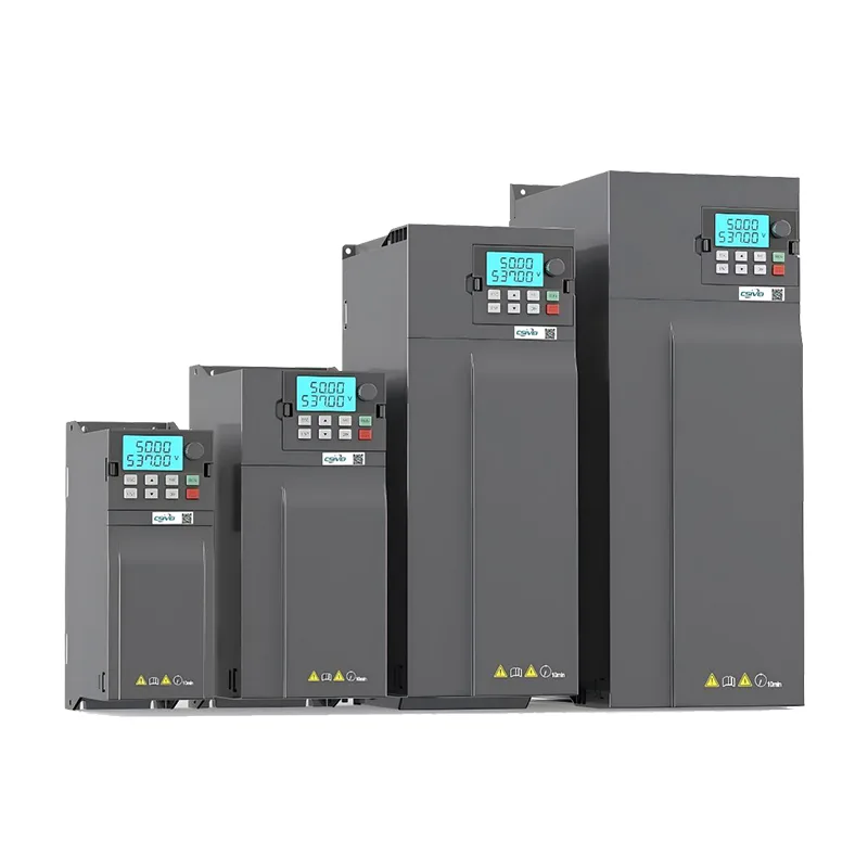
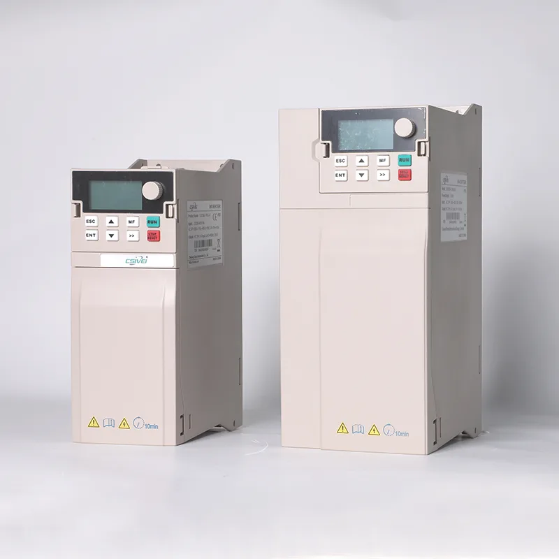
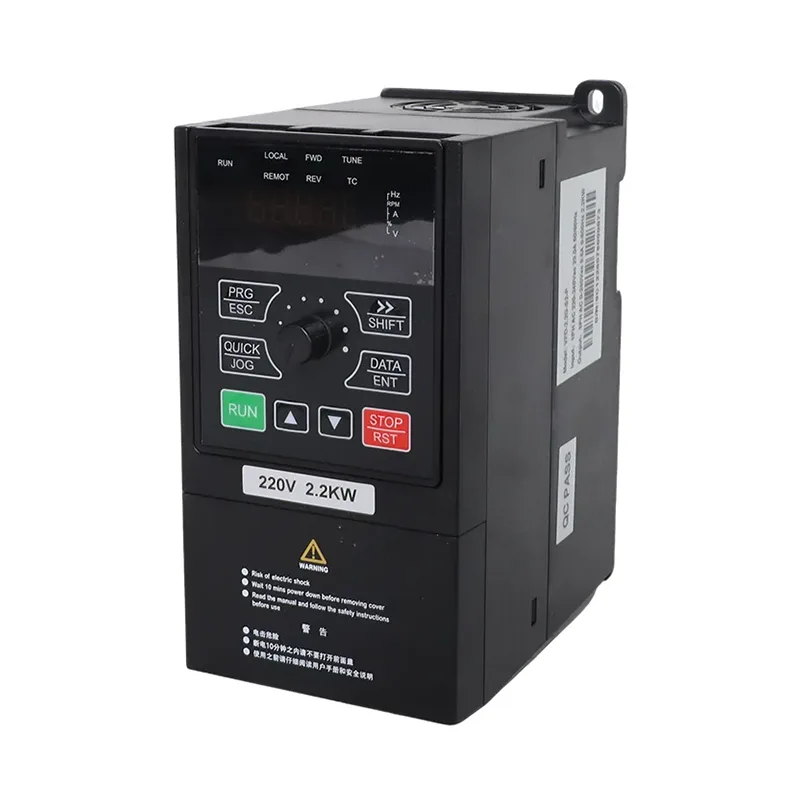
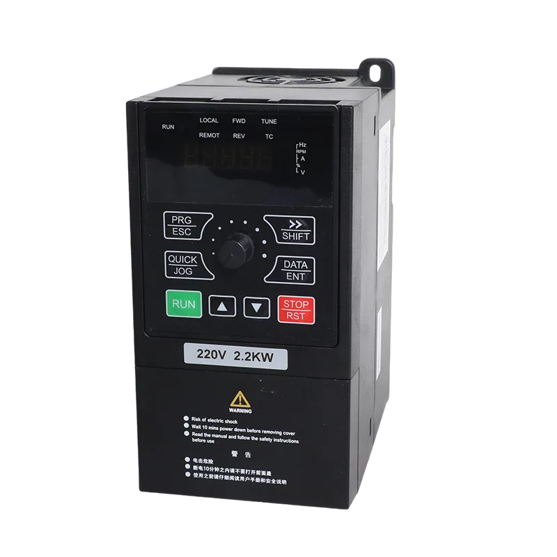
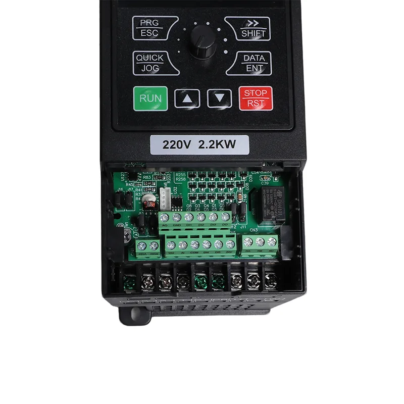
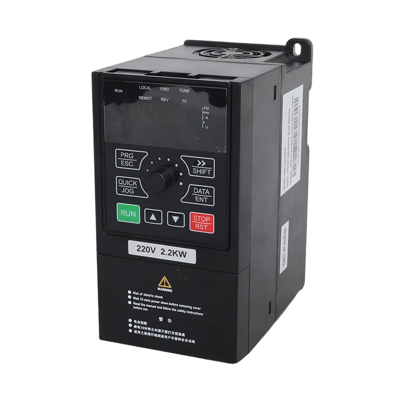
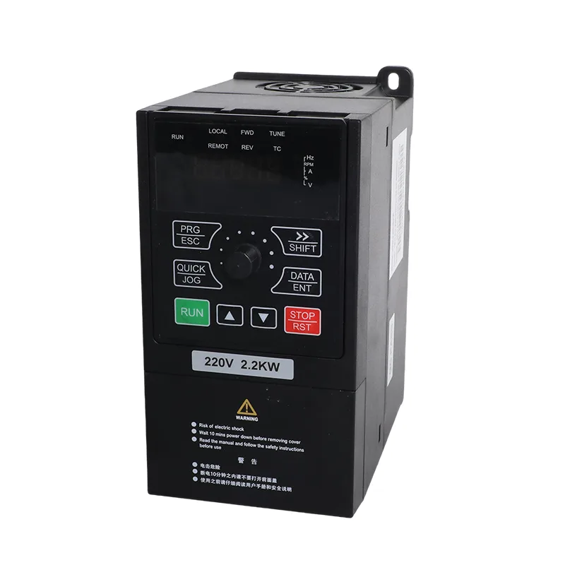
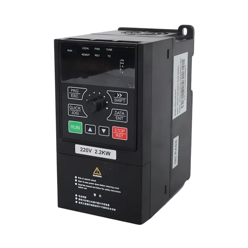
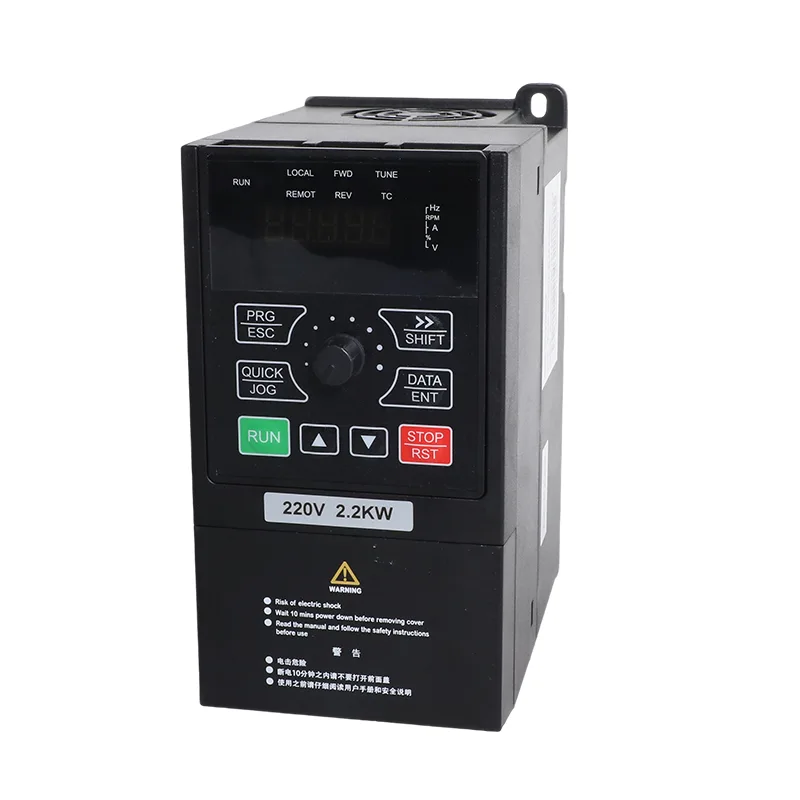
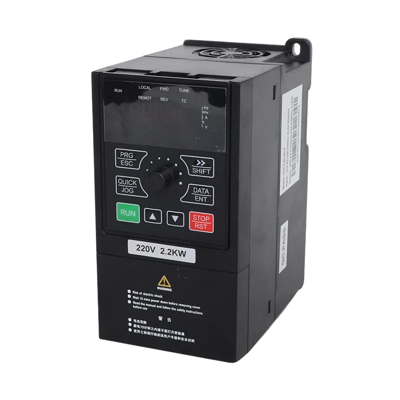
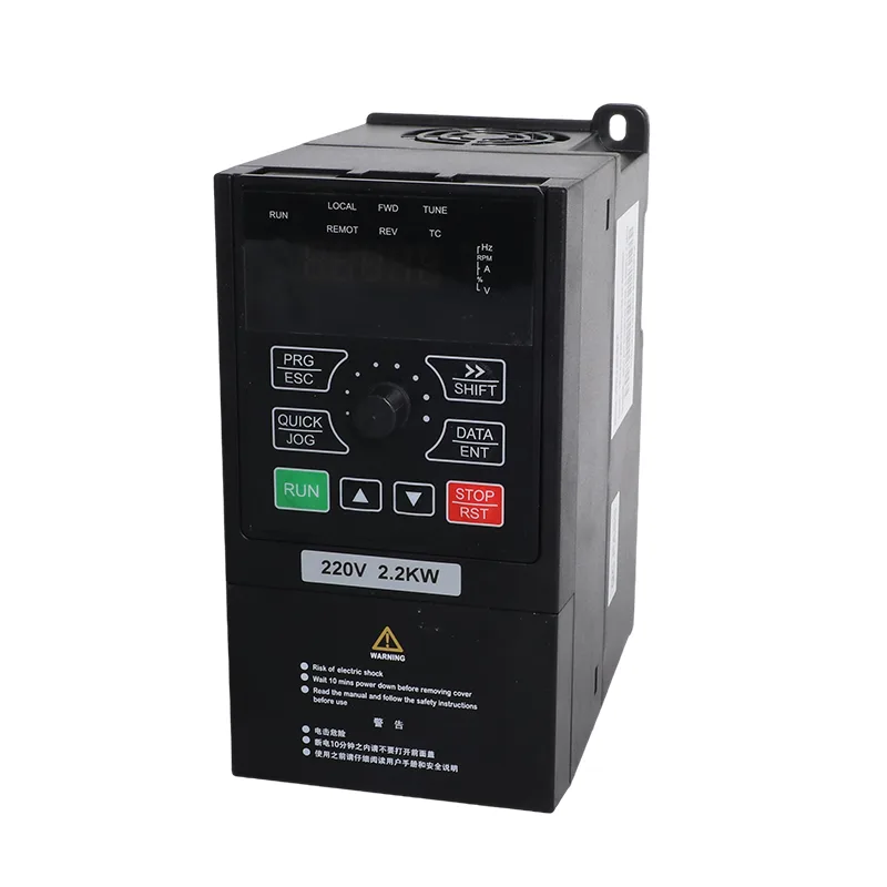
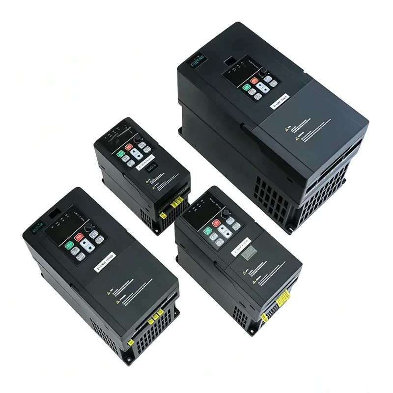
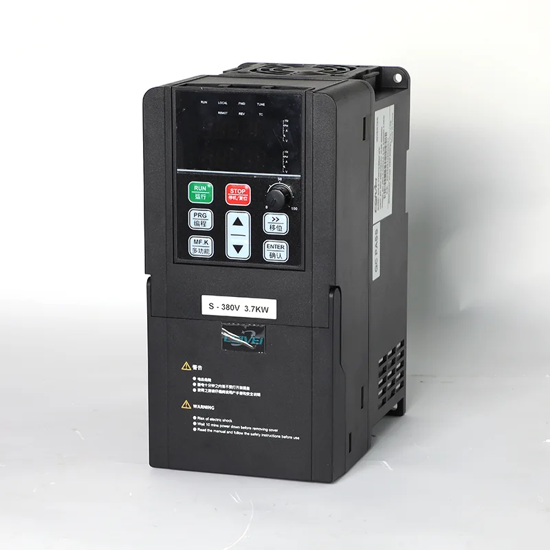
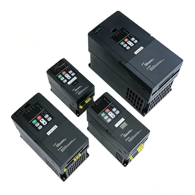
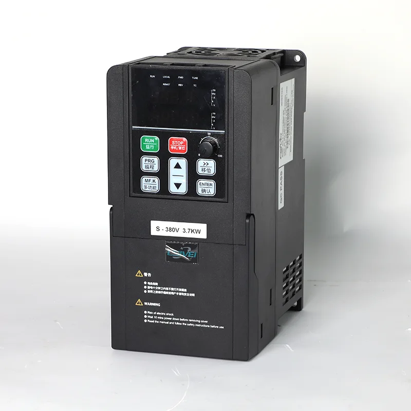
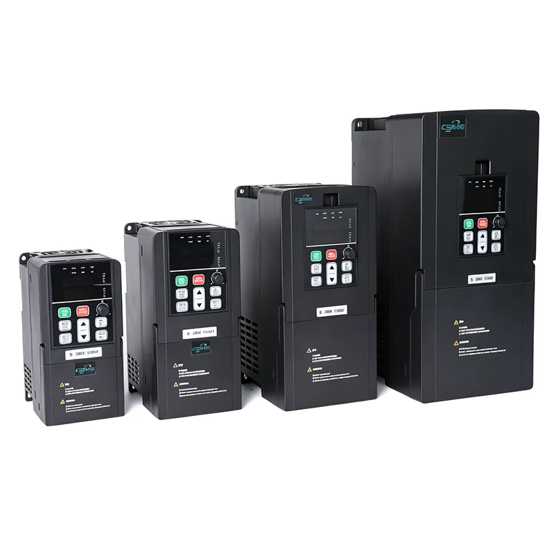
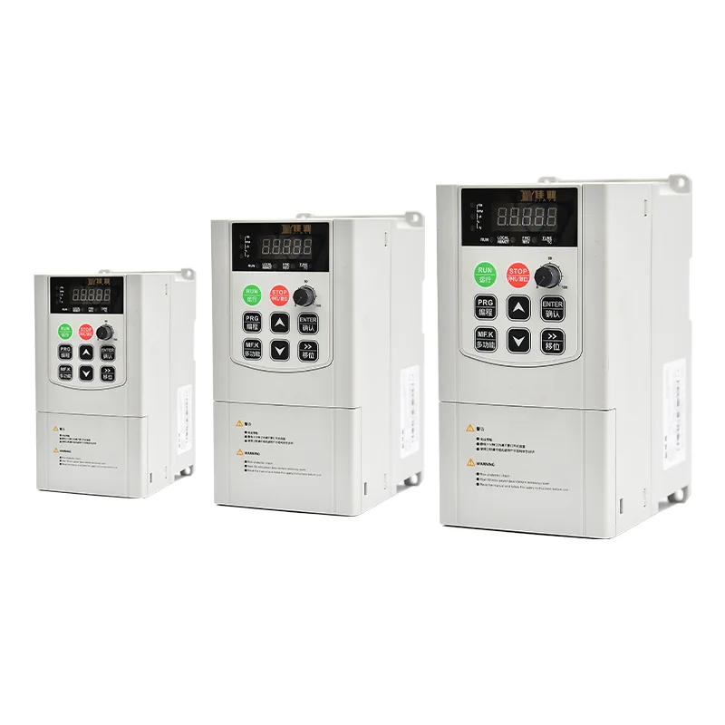
The CSIVEI iMaster VFD-PC10 series includes the VFD-PC10-7.5G-T4 and VFD-PC10-11G-T4-MK models for three-phase 380 V applications. The listed output currents are 17 A for the 7.5 kW model and 25 A for the 11 kW model. Both ratings are used in solar-powered pumping systems and compatible industrial motor applications, subject to the selected drive's electrical specifications.
In solar pump mode, the 7.5kW/11kW 3 Phase 380V Solar Pump and General Purpose Inverter VFD uses DC power from a photovoltaic array and applies maximum power point tracking (MPPT) to control the motor according to available solar input. In general-purpose mode, it provides variable-frequency motor control for compatible pumps and other equipment. The operating mode is selected through parameter P8-00 according to the required application and the supplied configuration.
Compared with a basic motor-speed controller, the listed PC10 functions also include water-level monitoring, underload detection and probe-fault reporting. These functions are relevant to pumping systems where the water source, storage tank and pump operation need to be monitored through the drive.
| Item | VFD-PC10-7.5G-T4 / -MK | VFD-PC10-11G-T4-MK |
| Applicable motor | 7.5 kW / 10 HP | 11 kW / 15 HP |
| Nominal capacity | 15 kVA | 30 kVA |
| Input current | 18.9 A | 27.8 A |
| Output current | 17 A | 25 A |
| AC input voltage | AC 3 PH 380 V (-15%) to 440 V (+10%) | |
| Max. DC input voltage | 900 VDC | |
| Recommended Voc range | 550 to 750 VDC | |
| Recommended MPPT range | 450 to 600 VDC | |
| Start voltage range | 300 to 900 VDC, parameter adjustable | |
| Noise level | 65 dBA max. |
Choose the model by comparing the motor's rated current with the inverter's output-current rating, rather than relying on motor power alone. Confirm the exact model suffix, input voltage requirements and applicable nameplate data before installation.
The reference configurations below show the module quantities listed for the two drive ratings. They provide a starting point for PV system design; the final arrangement must be verified against the selected module's electrical data, the site's minimum temperature and the pumping requirements.
| Model | 37±1 V modules, 250 W±5 Wp | 45±1 V modules, 300 W±5 Wp | ||
| Modules per string | Strings | Modules per string | Strings | |
| VFD-PC10-7.5G-T4 | 18 | 2 | 15 | 2 |
| VFD-PC10-11G-T4-MK | 18 | 3 | 15 | 3 |
| Item | Specification |
| Rated frequency | 50/60 Hz |
| Input frequency range | ±5% (47.5 to 63 Hz) |
| Output voltage | 0 to input voltage |
| Output frequency | 0.1 to 500 Hz |
| Maximum frequency | 0 to 500 Hz (SVC and V/F control) |
| Carrier frequency | 0.8 kHz to 8 kHz, adjusted automatically to load (up to 16 kHz supported) |
| Frequency resolution | Digital setting 0.01 Hz; analog setting 0.025% of maximum frequency |
| Control mode | Sensorless vector control (SVC); V/F control |
| Starting torque | 0.5 Hz / 150% (SVC) |
| Speed range | 1:100 (SVC) |
| Speed stability accuracy | ±0.5% (SVC) |
| Overload capacity | 150% rated current for 60 s; 170% for 12 s; 190% for 1.5 s |
| Torque boost | Automatic torque boost; manual boost 0.1% to 30.0% |
| V/F curve | Linear, multi-point, and square curve (1.2 / 1.4 / 1.6 / 1.8 / 2.0 power) |
| V/F separation | Full separation, half separation |
| Acceleration / deceleration | Linear or S-curve, 0.0 to 6500.0 s |
| DC braking | Start frequency 0.00 Hz to maximum frequency; time 0.0 to 36.0 s; current 0.0% to 100.0% |
| JOG control | JOG frequency 0.00 Hz to maximum frequency (default 5 Hz); accel/decel 0.0 to 6500.0 s |
| Built-in PID | Yes, for pressure, flow or temperature closed loop without an external controller |
| AVR | Output voltage held stable when grid voltage fluctuates |
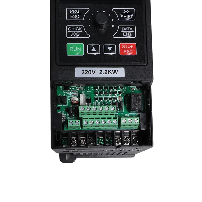
| Input terminals | 5 digital inputs, DI5 supports high-speed pulse up to 50 kHz; 1 analog input 0-10 V or 0-20 mA; 1 keypad potentiometer input |
| Output terminals | 1 high-speed pulse output up to 50 kHz; 1 relay output; 1 analog output 0-20 mA or 0-10 V |
| Communication | RS485, Modbus RTU |
| Protection | Motor short-circuit detection at power-on, output phase loss, over-current, over-voltage, under-voltage, over-temperature, overload, underload, weak light |
| Operating temperature | -10°C to 50°C; derate 1% per 1°C above 40°C |
| Storage temperature | -20°C to 60°C |
| Humidity | Below 95% RH, no condensation |
| Altitude | Below 1000 m; derate 1% per 100 m from 1000 to 3000 m |
| Vibration | Below 5.9 m/s² (0.6 g) |
| Enclosure | IP20, wall mount or cabinet, vertical installation |
| Distribution system | TN, TT |
| EMC / safety | IEC 61800-3 (C3); IEC 61800-5-1 |
The PC10 series information describes an automatic operating sequence for installations configured for solar and grid power. In the documented configuration, parameter P8-15 selects the supply-mode behaviour. With P8-15 set to 0, the drive operates on solar power when available and uses the grid according to the configured weak-light and changeover logic.
The supplied parameter information lists P8-16 as the grid-operation interval, with a default of 60 minutes, and P8-17 as the delay associated with returning to solar operation, with a default of 4 seconds. Confirm the supported sequence and parameter defaults against the manual for the exact model and firmware version before commissioning.
For a system using an AC backup source, the wiring and changeover arrangement must follow the applicable circuit diagram. Confirm whether external switching equipment is required; do not assume that the inverter alone performs every source-switching function.
For shared water supply, irrigation and aquaculture systems, pump operation may depend on both the water level in the storage tank and the availability of water at the source. The listed PC10 parameters provide functions related to water-level detection, underload monitoring and probe-fault diagnostics.
The supplied parameter information identifies P8-18 for AI water-level detection, P8-19 for the full-level threshold and P8-20 for the sleep delay. The configured level signal and threshold determine how the drive responds to the monitored tank condition. Sensor type, wiring and the actual control sequence should follow the applicable wiring diagram and parameter instructions.
The source-water protection information uses P8-24 for the underload detection level, P8-25 for the detection time and P8-26 for the reset setting. These parameters are relevant where a reduction in motor load is used to identify a possible lack of water or a related pump condition.
The supplied source identifies P8-22 as a probe-damage monitoring threshold and E43 as the corresponding probe-fault indication. Confirm the alarm definition and detection conditions in the relevant model manual when configuring or troubleshooting the system.
Water-level and underload functions depend on correct sensor selection, installation and parameter settings. They should be commissioned and tested under the conditions specified in the product documentation.
The supplied PC10 series information states that panel commands and communication commands can be retained across a power cycle. The actual restart behaviour should be checked against the configured command source, restart parameters and safety requirements of the application.
RS485 Modbus RTU is listed as the communication interface. The source identifies monitoring parameter U0-49 as the supply-mode status, with 0 indicating grid operation and 1 indicating solar operation. This information may be used by a compatible monitoring system after confirming the register definition and available status values in the applicable communication documentation.
Remote monitoring is useful when the drive operates at a water tank, irrigation station or other site where the controller is not continuously attended. The communication setup should be tested to confirm that the displayed status matches the actual operating state.
In general-purpose mode, the inverter provides variable-frequency motor control for compatible equipment. The listed control methods are sensorless vector control (SVC) and V/F control, with additional functions including built-in PID, adjustable acceleration and deceleration, JOG control and Modbus RTU communication.
The general-purpose configuration can be considered for compatible applications such as mine dewatering, quarry dust suppression, industrial circulation and process pumps. The model must be matched to the motor's rated current, load characteristics, acceleration requirements and operating duty.
Parameter P8-00 is identified in the supplied information as the operating-mode selection parameter. The mode should be configured according to the actual application and the instructions for the supplied model. Any change between solar pump and general-purpose operation must follow the prescribed parameter-setting and commissioning procedure.
For borehole or river-water pumping to a distribution tank, the drive's solar operation and listed level-monitoring functions can be considered as part of the system design. Motor rating, pumping head, required water volume and tank-level control should be defined before the drive is selected.
Shared irrigation systems may use a central pump to supply multiple fields or irrigation zones. Selection should reflect the required flow, total dynamic head, daily operating schedule and the availability of solar or grid power.
Water-exchange and circulation pumps at aquaculture sites can use variable-frequency control where the motor and pump arrangement are compatible. The required pumping schedule and water-management controls should be considered along with the site's power supply.
In general-purpose mode, the drive can be evaluated for compatible mine dewatering, pit-water management and dust-suppression pumping equipment. Verify the motor rating, load conditions, environmental requirements and required control method for the specific installation.
The general-purpose configuration can be considered for compatible process-water circulation, cooling-tower make-up and other industrial pumping duties. The required flow, operating pressure and motor characteristics should be evaluated as part of the system design.
| Item | Specification |
|---|---|
| Rated frequency | 50/60 Hz |
| Input frequency range | ±5% (47.5 to 63 Hz) |
| Output voltage | 0 to input voltage |
| Output frequency | 0.1 to 500 Hz |
| Maximum frequency | 0 to 500 Hz (SVC and V/F control) |
| Carrier frequency | 0.8 kHz to 8 kHz, adjusted automatically to load; up to 16 kHz supported |
| Frequency resolution | Digital setting 0.01 Hz; analog setting 0.025% of maximum frequency |
| Control mode | Sensorless vector control (SVC); V/F control |
| Starting torque | 0.5 Hz / 150% (SVC) |
| Speed range | 1:100 (SVC) |
| Speed stability accuracy | ±0.5% (SVC) |
| Overload capacity | 150% rated current for 60 s; 170% for 12 s; 190% for 1.5 s |
| Torque boost | Automatic torque boost; manual boost 0.1% to 30.0% |
| V/F curve | Linear, multi-point, and square curve (1.2 / 1.4 / 1.6 / 1.8 / 2.0 power) |
| V/F separation | Full separation, half separation |
| Acceleration / deceleration | Linear or S-curve, 0.0 to 6500.0 s |
| DC braking | Start frequency 0.00 Hz to maximum frequency; time 0.0 to 36.0 s; current 0.0% to 100.0% |
| JOG control | JOG frequency 0.00 Hz to maximum frequency (default 5 Hz); accel/decel 0.0 to 6500.0 s |
| Built-in PID | Yes, for pressure, flow or temperature closed loop without an external controller |
| AVR | Output voltage held stable when grid voltage fluctuates |
| Input terminals | 5 digital inputs, DI5 supports high-speed pulse up to 50 kHz; 1 analog input 0-10 V or 0-20 mA; 1 keypad potentiometer input |
| Output terminals | 1 high-speed pulse output up to 50 kHz; 1 relay output; 1 analog output 0-20 mA or 0-10 V |
| Communication | RS485, Modbus RTU |
| Protection | Motor short-circuit detection at power-on, output phase loss, over-current, over-voltage, under-voltage, over-temperature, overload, underload, weak light |
| Operating temperature | -10°C to 50°C; derate 1% per 1°C above 40°C |
| Storage temperature | -20°C to 60°C |
| Humidity | Below 95% RH, no condensation |
| Altitude | Below 1000 m; derate 1% per 100 m from 1000 to 3000 m |
| Vibration | Below 5.9 m/s² (0.6 g) |
| Enclosure | IP20, wall mount or cabinet, vertical installation |
| Distribution system | TN, TT |
| EMC / safety | IEC 61800-3 (C3); IEC 61800-5-1 |
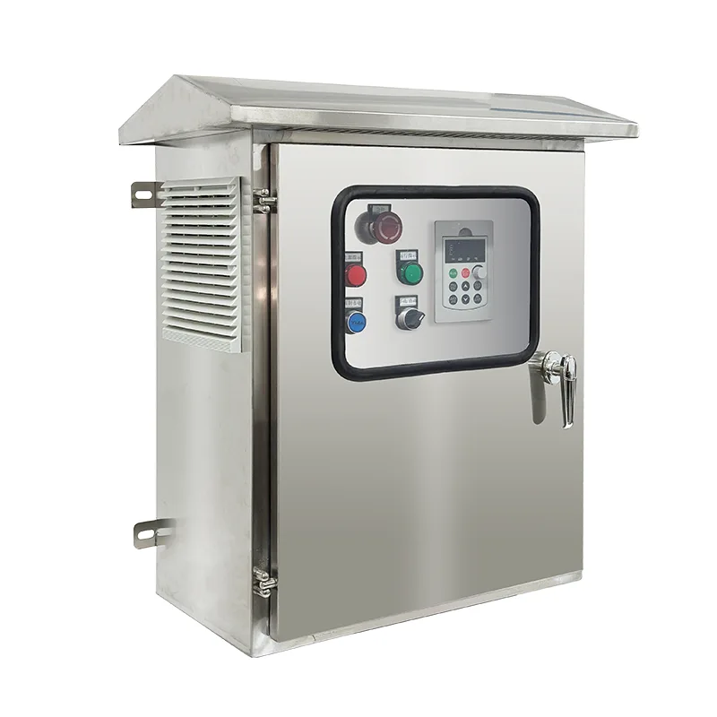
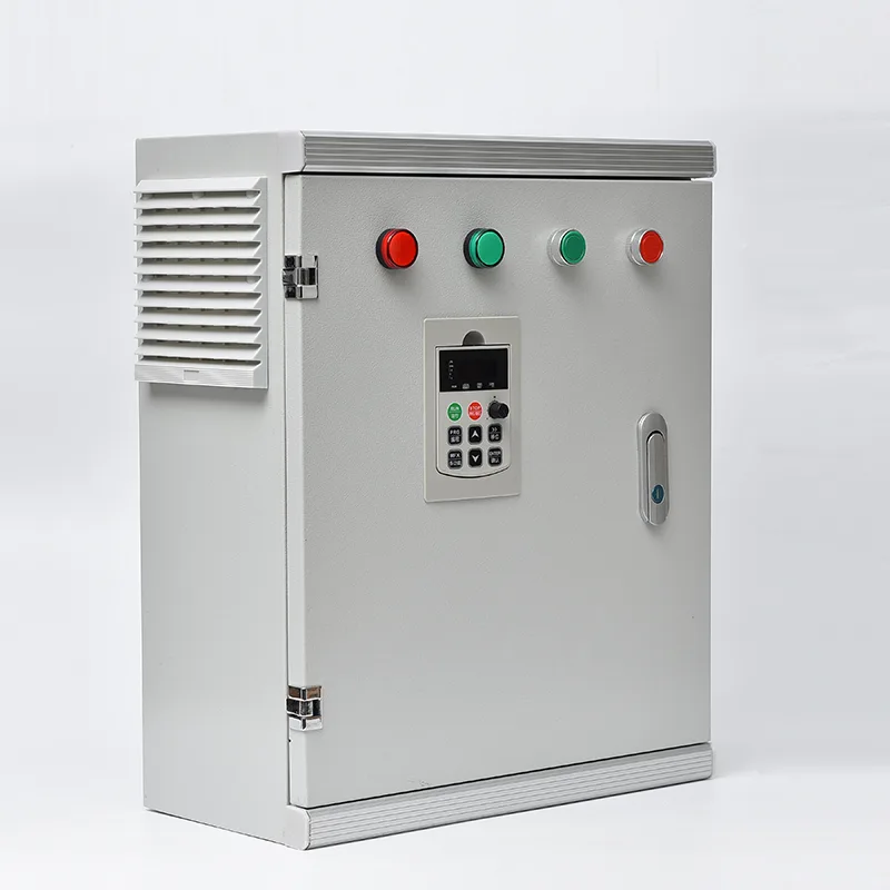
The enclosure is rated IP20 and does not provide protection against water ingress. The drive should be installed in a suitable indoor or protective enclosure environment with adequate ventilation and in accordance with its temperature, humidity and installation requirements.
The supplied reference configurations specify three strings of 18 modules rated at 250 Wp or three strings of 15 modules rated at 300 Wp. These arrangements correspond to 54 modules or 45 modules, respectively, and a calculated nominal array power of 13.5 kWp in either case. Final string design must be verified against the module datasheet, the site's minimum temperature and the inverter's DC voltage limits.
The supplied specification lists a maximum noise level of 65 dBA. Whether additional acoustic treatment is necessary depends on the installation location, room acoustics, operating equipment and applicable noise requirements. Consider the installation environment when positioning the drive in an occupied building or enclosed equipment room.
The general-purpose configuration should be matched to the total load and the supported control method. For vector-control applications, confirm the applicable motor arrangement in the manual. Running multiple motors from one drive requires the combined current to remain within the drive rating and each motor to have appropriate overload protection. Follow the manufacturer's instructions for the selected control mode.
The supplied information identifies monitoring parameter U0-49 as the supply-mode indicator, with 0 representing grid operation and 1 representing solar operation. The parameter may be read over Modbus RTU where supported. Confirm the register definition and communication settings against the applicable manual before integrating it into a remote monitoring system.
Keep the heatsink and cooling fan clear of dust, inspect terminals and wiring connections according to the maintenance schedule, and monitor ambient temperature and ventilation. The listed operating temperature range is -10°C to 50°C, with derating above 40°C. The supplied altitude guidance also specifies derating above 1000 m. Follow the exact model's instructions for inspection intervals and maintenance procedures.
No. The supplied PC10 series information lists solar pump mode and general-purpose inverter mode. Solar pump operation includes MPPT and the documented pumping-related protection functions, while general-purpose operation supports SVC or V/F motor control, PID and Modbus RTU. Parameter P8-00 is identified as the mode-selection parameter. Confirm the permitted setting and mode-change procedure in the model-specific manual.


Address
No. 3788, Liujiang Road, Liushi Town, Yueqing City, Wenzhou City, Zhejiang Province, China
Tel
If you have any enquiry about quotation or cooperation, please feel free to email us at sanchia@csivei.com or use the following inquiry form.Our sales representative will contact you within 24 hours. Thank you for your interest in our products.
WhatsApp:8615705777705