Whatsapp
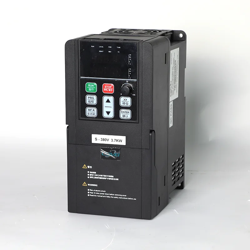
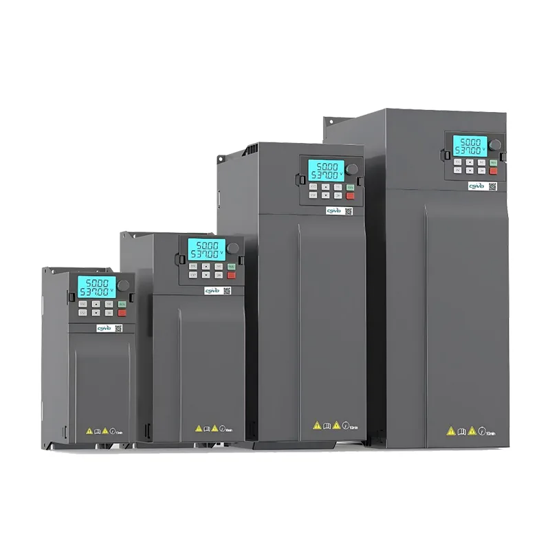
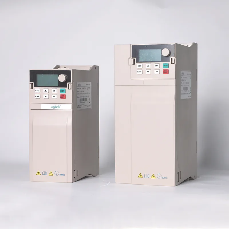
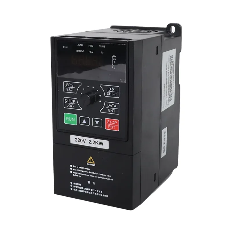
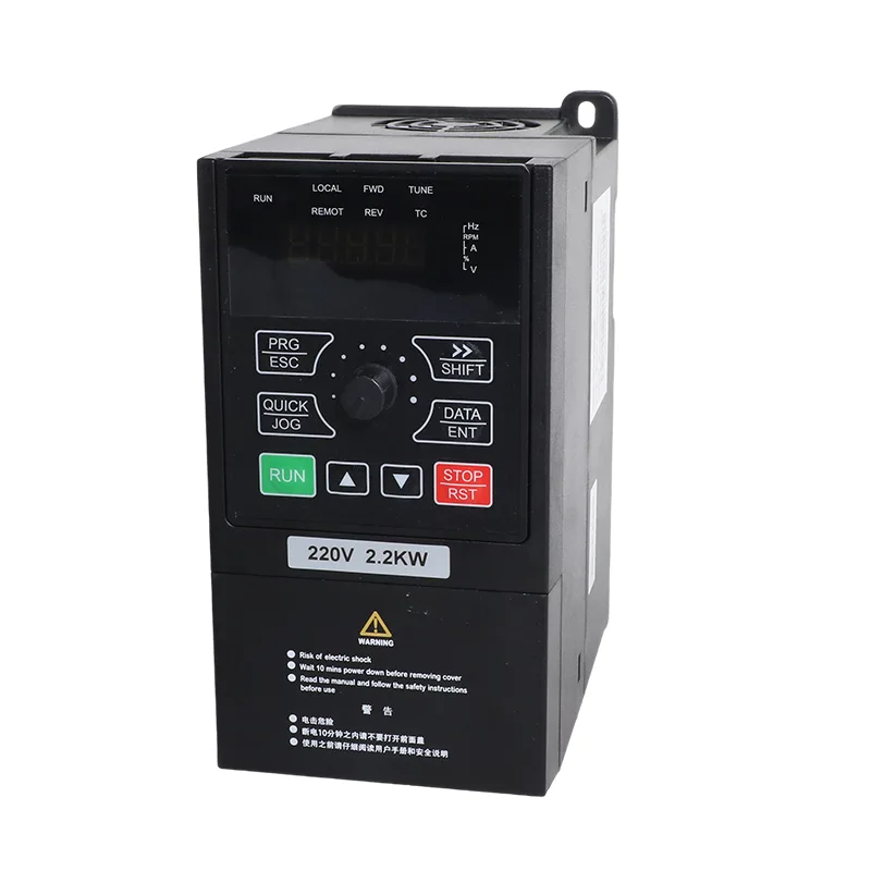
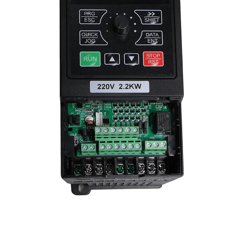
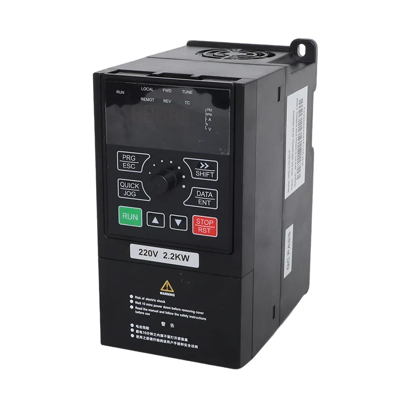
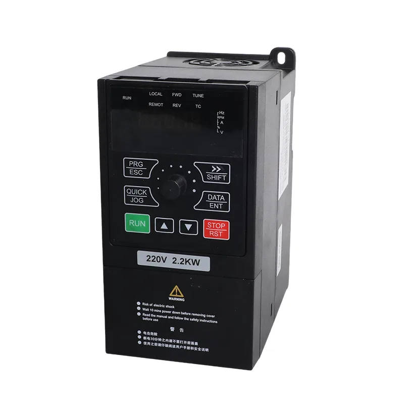
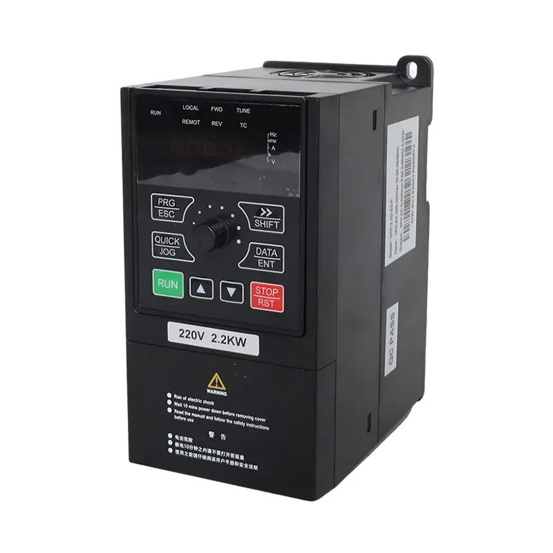
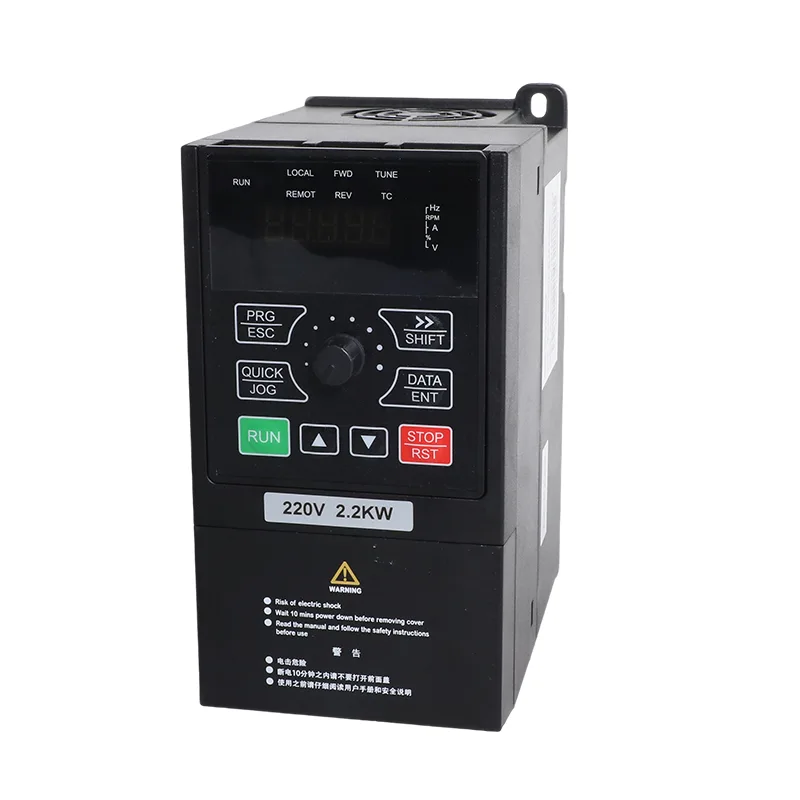
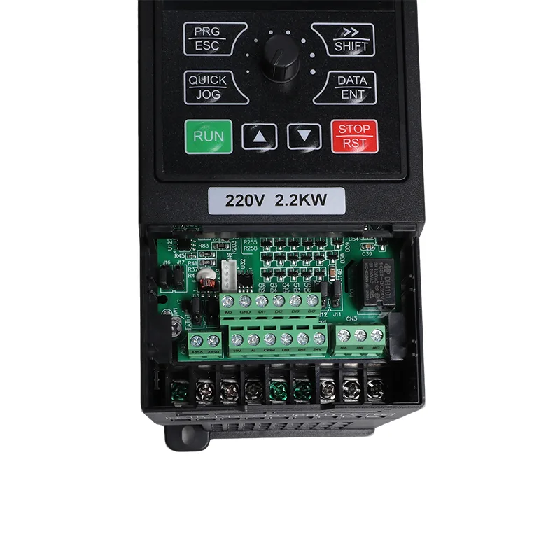
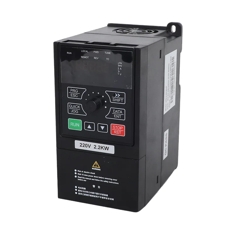
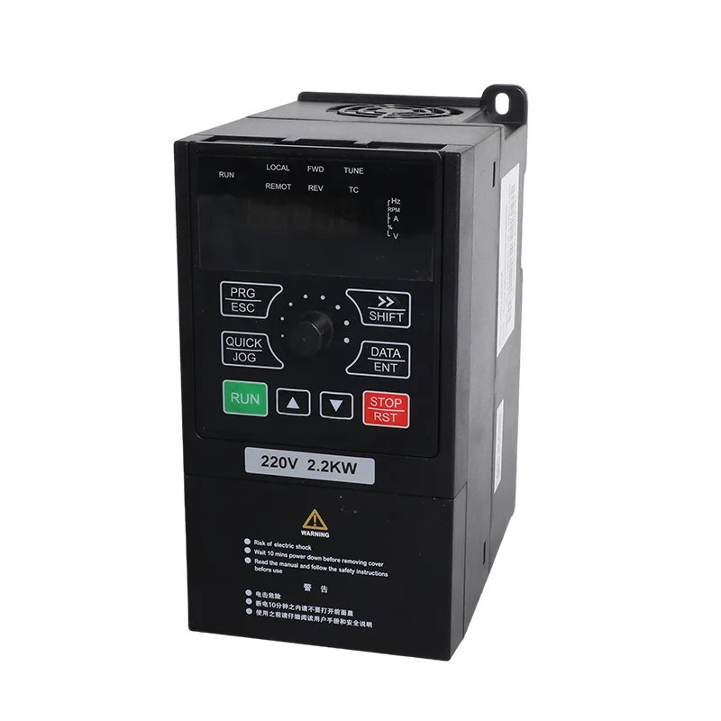
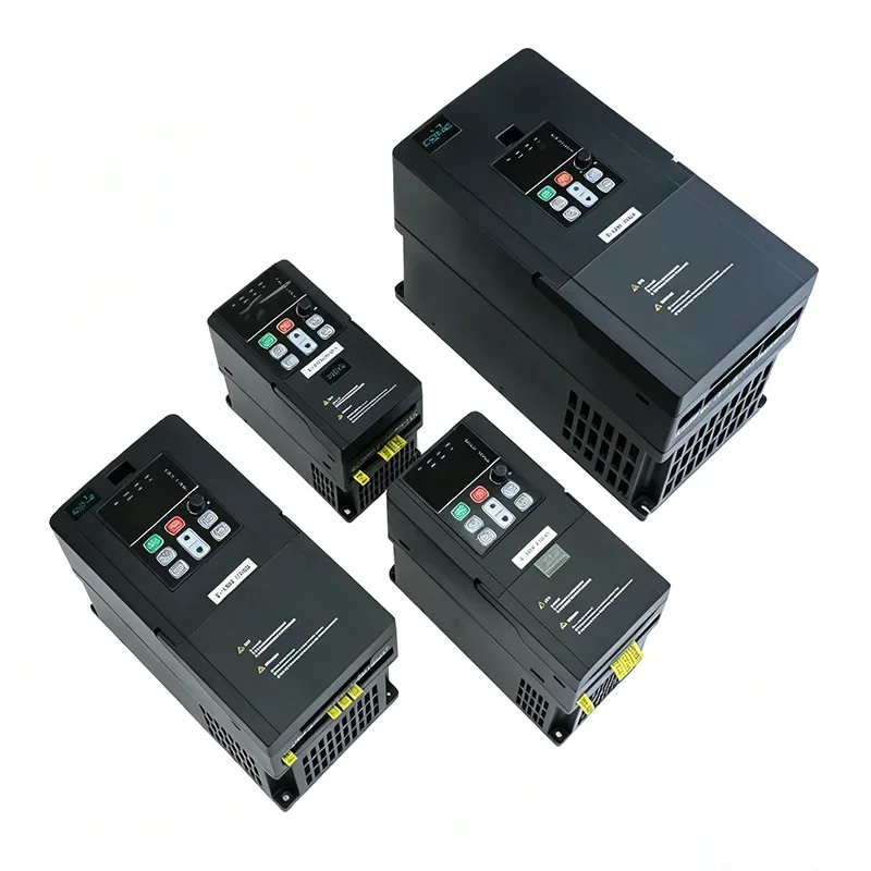
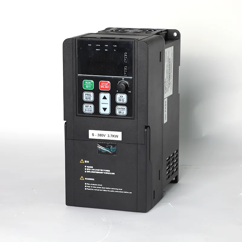
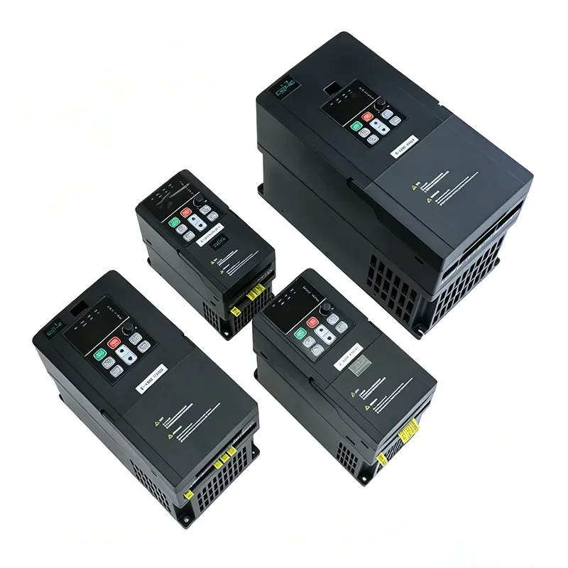
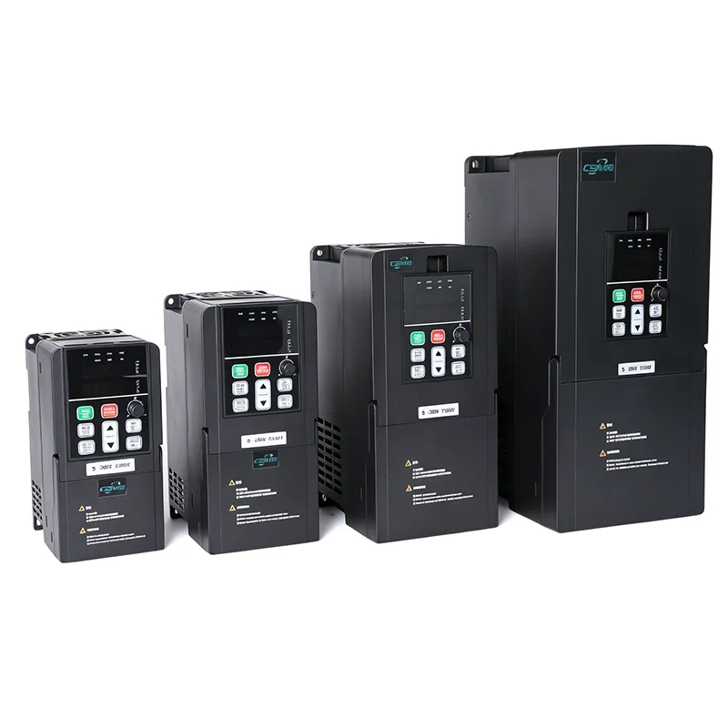
CSIVEI manufactures the 4.0kW/5.5kW 3 Phase 380V Solar Pump and General Purpose Inverter VFD for three-phase motor systems requiring photovoltaic pump control or conventional variable-frequency operation. The VFD-PC10-4.0G-T4 and VFD-PC10-5.5G-T4 models cover 4.0 kW and 5.5 kW motor ratings, with rated output currents of 9 A and 13 A, respectively. Both models accept three-phase AC input from 380 V (-15%) to 440 V (+10%).
The series combines solar pump control with general-purpose motor control in one inverter platform. The selected operating mode determines how the drive manages its power source and motor operation, while the built-in control and protection functions support pump installations as well as compatible fans, blowers and process machinery. When requesting a quotation, provide the motor nameplate ratings and intended application to help establish the appropriate model and configuration.

The 4.0kW/5.5kW 3 Phase 380V Solar Pump and General Purpose Inverter VFD supports two operating modes selected through parameter P8-00.
Solar pump mode — P8-00 = 1
In this mode, the drive uses photovoltaic power to operate a compatible pump, with MPPT control and automatic grid changeover functions. When solar power is insufficient, the configured changeover sequence allows the system to use grid power. This arrangement is suitable for agricultural irrigation, borehole water supply and other pumping applications where solar energy is available during part of the operating day.
General-purpose mode — P8-00 = 0
In this mode, the drive operates as a conventional variable-frequency inverter for compatible motors, including pumps, fans, blowers and process machinery. Sensorless vector control (SVC) and V/F control support different motor-control requirements without using the photovoltaic pumping function.
CSIVEI can configure the operating mode before shipment. The mode can also be changed by adjusting P8-00, allowing the drive to be reassigned to a different application when the installation requirements change. The relevant parameters and wiring must match the selected operating mode.
The recommended photovoltaic array depends on the inverter rating and the electrical characteristics of the modules. Table B provides module and string configurations for two module options: 37±1 V modules rated at 250 W±5 Wp, and 45±1 V modules rated at 300 W±5 Wp.
The principal DC-side limits are:
The series-string voltage must be assessed against the actual module open-circuit voltage and expected operating temperatures. Parallel-string arrangements should follow the recommended configuration and the applicable DC protection requirements. Keeping the array within the specified voltage limits is essential for correct inverter operation.
Both models share the same housing dimensions of 245 × 142 × 181.3 mm and a 107 × 235 mm mounting pattern. The compact wall-mount or cabinet-mount design allows the drive to be incorporated into a pump-control installation without changing the motor rating or application solely to accommodate the inverter.
The drive has an IP20 enclosure and is intended for vertical installation in a suitable protected location. Installation planning should account for the operating environment, electrical protection, cable routing and access for commissioning and maintenance. The general operating temperature range is -10°C to 50°C, with derating required above 40°C.
| Item | VFD-PC10-4.0G-T4 / -MK | VFD-PC10-5.5G-T4 / -MK |
| Applicable motor | 4.0 kW / 5 HP | 5.5 kW / 7.5 HP |
| Nominal capacity | 6 kVA | 11 kVA |
| Input current | 10.5 A | 13.9 A |
| Output current | 9 A | 13 A |
| AC input voltage | AC 3 PH 380 V (-15%) to 440 V (+10%) | |
| Max. DC input voltage | 900 VDC | |
| Recommended Voc range | 550 to 750 VDC | |
| Recommended MPPT range | 450 to 600 VDC | |
| Start voltage range | 300 to 900 VDC, parameter adjustable | |
| Output frequency range | 0 to 500.00 Hz | |
| Noise level | 50 dBA max. |
| Model | 37±1 V modules, 250 W±5 Wp | 45±1 V modules, 300 W±5 Wp | ||
| Modules per string | Strings | Modules per string | Strings | |
| VFD-PC10-4.0G-T4 | 20 | 1 | 16 | 1 |
| VFD-PC10-5.5G-T4 | 18 | 2 | 15 | 2 |
| Item | Specification |
| Rated frequency | 50/60 Hz |
| Input frequency range | ±5% (47.5 to 63 Hz) |
| Output voltage | 0 to input voltage |
| Output frequency | 0.1 to 500 Hz |
| Maximum frequency | 0 to 500 Hz (SVC and V/F control) |
| Carrier frequency | 0.8 kHz to 8 kHz, adjusted automatically to load (up to 16 kHz supported) |
| Frequency resolution | Digital setting 0.01 Hz; analog setting 0.025% of maximum frequency |
| Control mode | Sensorless vector control (SVC); V/F control |
| Starting torque | 0.5 Hz / 150% (SVC) |
| Speed range | 1:100 (SVC) |
| Speed stability accuracy | ±0.5% (SVC) |
| Overload capacity | 150% rated current for 60 s; 170% for 12 s; 190% for 1.5 s |
| Torque boost | Automatic torque boost; manual boost 0.1% to 30.0% |
| V/F curve | Linear, multi-point, and square curve (1.2 / 1.4 / 1.6 / 1.8 / 2.0 power) |
| V/F separation | Full separation, half separation |
| Acceleration / deceleration | Linear or S-curve, 0.0 to 6500.0 s |
| DC braking | Start frequency 0.00 Hz to maximum frequency; time 0.0 to 36.0 s; current 0.0% to 100.0% |
| JOG control | JOG frequency 0.00 Hz to maximum frequency (default 5 Hz); accel/decel 0.0 to 6500.0 s |
| Built-in PID | Yes, for pressure, flow or temperature closed loop without an external controller |
| AVR | Output voltage held stable when grid voltage fluctuates |
| Input terminals | 5 digital inputs, DI5 supports high-speed pulse up to 50 kHz; 1 analog input 0-10 V or 0-20 mA; 1 keypad potentiometer input |
| Output terminals | 1 high-speed pulse output up to 50 kHz; 1 relay output; 1 analog output 0-20 mA or 0-10 V |
| Communication | RS485, Modbus RTU |
| Protection | Motor short-circuit detection at power-on, output phase loss, over-current, over-voltage, under-voltage, over-temperature, overload, underload, weak light |
| Operating temperature | -10°C to 50°C; derate 1% per 1°C above 40°C |
| Storage temperature | -20°C to 60°C |
| Humidity | Below 95% RH, no condensation |
| Altitude | Below 1000 m; derate 1% per 100 m from 1000 to 3000 m |
| Vibration | Below 5.9 m/s² (0.6 g) |
| Enclosure | IP20, wall mount or cabinet, vertical installation |
| Distribution system | TN, TT |
| EMC / safety | IEC 61800-3 (C3); IEC 61800-5-1 |
The iMaster VFD-PC10 series combines solar pump management with variable-frequency motor control, making the 4.0 kW and 5.5 kW models suitable for a range of water-handling and industrial applications.
For installations that need both photovoltaic pumping and conventional motor control, the 4.0kW/5.5kW 3 Phase 380V Solar Pump and General Purpose Inverter VFD can be specified for the intended duty and configured accordingly.
For water systems that require pressure regulation, the built-in PID function can use a suitable feedback signal to adjust motor operation around a configured setpoint. With an appropriately selected pressure transmitter and correctly configured control parameters, the drive can regulate system pressure as demand changes. The final settings depend on the pump, motor and application.
Built-in PID supports closed-loop pressure, flow or temperature control. Setpoint and feedback sources are selected through the available FC-group parameters.
General-purpose mode supports SVC and V/F control, overload capacity of 150% for 60 seconds, and RS485 communication with Modbus RTU.
P8-00 = 1: solar pump mode. P8-00 = 0: general-purpose inverter mode. CSIVEI can set the operating mode and requested parameters before shipment.
The 4 kW unit runs a single string, so the string is built longer to reach the 550 to 750 VDC window. The 5.5 kW unit needs roughly double the array wattage, which is easier to reach with two parallel strings of 18. Both stay under the 900 VDC maximum.
Yes, and it is the most common installation. Leave the pump and cabling alone, add the array and the DC breaker, and wire the existing supply to R, S and T. Set P8-15 to 0 for automatic switching. Solar carries the daytime load and the grid takes over when there is not enough sun.
Fit a float or level switch to DI2 or DI3. Terminal polarity is set in F6-10 so either contact arrangement works. You can also use AI water level detection by setting P8-18 to 1 and adjusting the full threshold in P8-19 and the sleep delay in P8-20.
The common ones are A01 weak solar power, A02 tank full, A03 lack of water and A04 motor underload. Hardware faults E01 to E30 cover overcurrent, overvoltage, undervoltage, phase loss and overtemperature, with E43 for a failed level probe and E44 for an underload condition that does not clear.
Yes. Output phase loss protection and motor short-circuit detection at power-on are standard, along with overcurrent, overvoltage, undervoltage, overtemperature and overload.
Yes. In general-purpose mode it is a standard three-phase inverter for fans, blowers, compressors and process pumps, with SVC or V/F control, PID and Modbus. Order it in that mode and it arrives configured for the job. And a unit bought in solar pump mode can be moved across afterwards with P8-00.
Yes. Tell us the motor ratings, the panel configuration and any site-specific settings you want, and we load them before the unit leaves. That saves commissioning time on site and it is the reason many distributors buy configured rather than default.


Address
No. 3788, Liujiang Road, Liushi Town, Yueqing City, Wenzhou City, Zhejiang Province, China
Tel
If you have any enquiry about quotation or cooperation, please feel free to email us at sanchia@csivei.com or use the following inquiry form.Our sales representative will contact you within 24 hours. Thank you for your interest in our products.
WhatsApp:8615705777705