Whatsapp
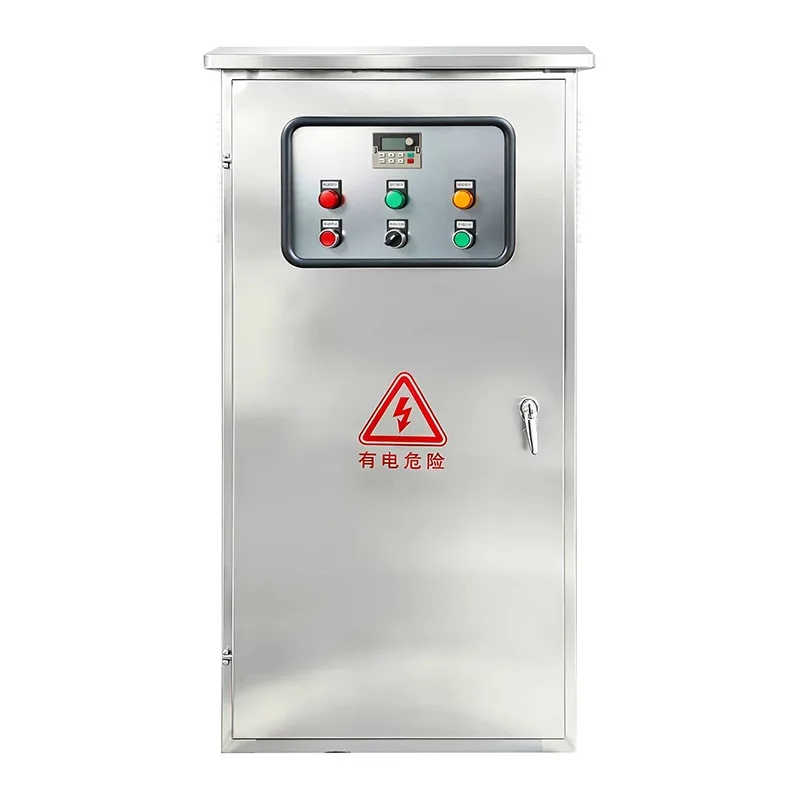
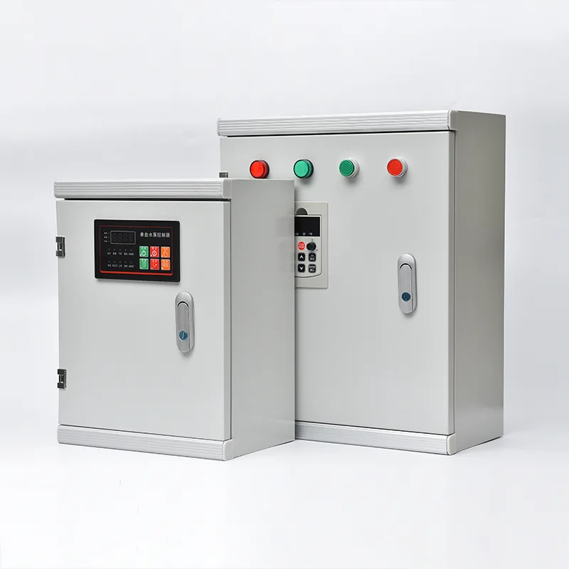
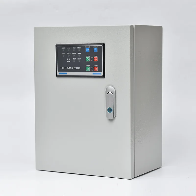
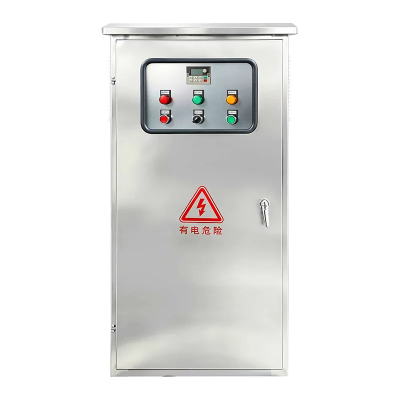
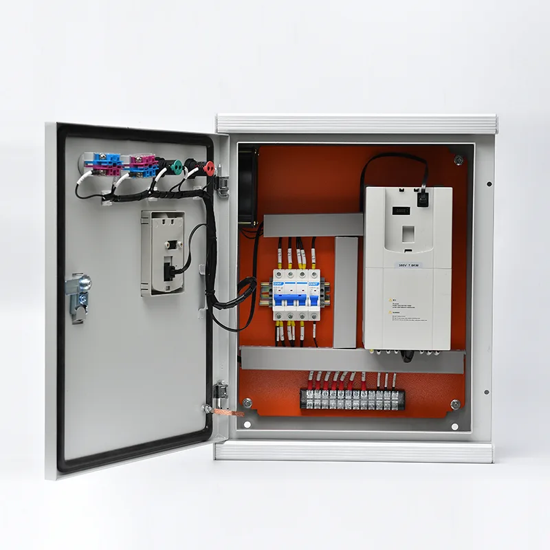
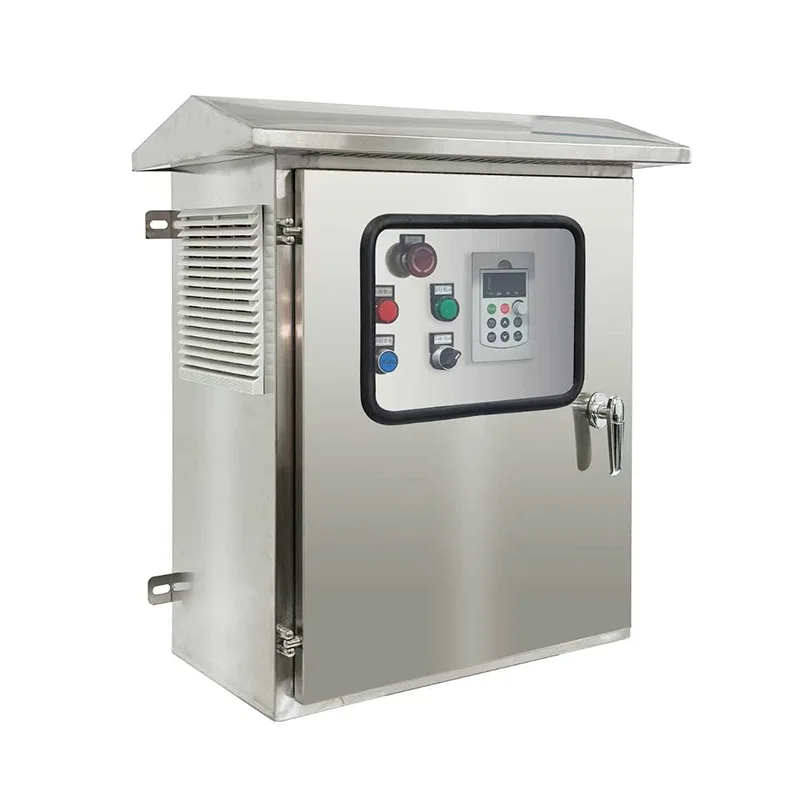
As a professional manufacturer in China, Csivei would like to provide you quality Motor Control Center Cabinet, which is a multi-section, front-access floor-standing assembly with a horizontal busbar system rated 400A to 6300A and short-circuit withstand up to 100kA. Each vertical section accepts withdrawable or fixed functional units: DOL, star-delta, soft starter, or VFD motor starters, plus feeder breakers and control power modules. Withdrawable units allow a faulty starter to be isolated, withdrawn, and replaced in minutes without de-energising the entire MCC. Internal segregation is available in Form 2, Form 3, or Form 4 per IEC 61439, separating busbars from functional units and terminals. Motor circuits are designed for Type 2 co-ordination per IEC 60947-4-1, ensuring no damage to starter components following a motor short-circuit fault. Communication via Profibus, Profinet, Modbus RTU/TCP, or Ethernet/IP transmits motor status, current, run hours, energy, and diagnostics to the plant DCS or SCADA. The enclosure is IP42 to IP55 rated in galvanised steel with powder-coated finish, suitable for indoor electrical rooms and dusty industrial environments.
Wherever dozens or hundreds of motors must be reliably powered, protected, and controlled from a central location, the Solar Pump Control System provides the structured, modular backbone for industrial electrical distribution.
Municipal and industrial water treatment facilities operate extensive motor fleets — raw water intake pumps, aeration blowers, clarifier drives, sludge handling, chemical dosing pumps, and high-lift distribution pumps — often numbering over a hundred motors across a single site. A Motor Control Centre consolidates all motor starters and drives into one or more centrally located MCC rooms, with each functional unit dedicated to a specific motor. Standardised drawer-type starter units for pumps and blowers allow a faulty unit to be withdrawn and replaced in minutes, restoring treatment process continuity. Integration with the plant SCADA system via redundant communication networks provides operators with real-time motor status, run hours, and energy consumption on every drive.
Refineries, gas processing plants, and petrochemical complexes operate in hazardous areas with stringent safety requirements. MCC Panels for these environments are typically installed in pressurised or purged electrical rooms away from process areas. Motor circuits are engineered for critical rotating equipment — crude oil pumps, product transfer pumps, cooling water circulation pumps, fin-fan cooler motors, and gas compressors. Form 3 or Form 4 internal segregation separates each motor starter unit from the main busbars and adjacent units, preventing an internal arc fault in one starter from propagating to others. Explosion-proof motor protection relays and certified current-limiting fuses ensure safe isolation of motors in classified zones.
Thermal and hydropower stations depend on MCCs to manage auxiliary motor-driven systems essential to generation — boiler feed pumps, condenser cooling water pumps, forced-draught and induced-draught fans, coal handling conveyors, and fuel oil pumps. The MCC's high short-circuit withstand rating (typically 65kA to 100kA) is critical in power station auxiliary boards where the fault level from the station auxiliary transformer can be severe. Redundant incoming supply sections with automatic transfer switching support the plant's black-start and unit shutdown critical power requirements.
Copper, gold, iron ore, and coal processing plants rely on MCCs to control crushers, grinding mills, flotation cells, thickener drives, conveyor systems, and slurry pumps — equipment that frequently starts under heavy load and operates in dusty, wet environments. The MCC enclosure is specified with enhanced dust and moisture protection (IP54/IP55) and often includes internal anti-condensation heaters for installations in unheated processing buildings. Motor protection relays with advanced thermal modelling ensure that large mill and crusher motors are not tripped unnecessarily during process overload conditions.
Continuous process industries such as paper mills and steel rolling mills operate hundreds of motors across long production lines, with motor failure potentially stopping the entire line. MCC Panels in these facilities incorporate withdrawable starter units that permit motor circuit servicing without de-energising the entire MCC section — the unit is simply isolated, withdrawn, and replaced with a spare while the main busbars remain live. Fieldbus communication from each starter unit to the DCS provides detailed motor diagnostics that enable scheduled change-out before unexpected failure.
Airports, convention centres, and large commercial complexes use MCCs to centralise control of all HVAC motor loads — chillers, cooling towers, chilled water pumps, air handling units, and smoke extract fans. Integration with the Building Management System enables duty cycling, night setback, and energy-optimised control across the entire motor fleet from a single control room.
The Motor Control Center Cabinet is a type-tested low-voltage switchgear assembly engineered for safe, modular motor control with a focus on operational uptime, personnel protection, and maintainability.
The MCC is constructed as a multi-section, floor-standing frame from folded and bolted galvanised steel profiles, with each section typically 600mm, 800mm, or 1000mm wide. The main horizontal busbar runs through the full length of the MCC in a dedicated top or rear compartment, fabricated from tin-plated copper or aluminium and sized for the rated continuous current (400A to 6300A). Busbar joints are bolted and torqued with Belleville washers to maintain contact force over thermal cycling. The vertical busbar in each section distributes power to the individual functional units via plug-in spring-loaded contacts, eliminating the need for wired connections between the busbar and each starter unit. Short-circuit withstand rating — verified through type testing — ensures the busbar system and its supports can endure the electromagnetic forces of a fault without deformation or contact separation.
Motor starter units are available in fixed (bolted) or withdrawable (drawer-type) configurations. Withdrawable units are the standard offering for critical processes, allowing a starter to be electrically isolated, mechanically withdrawn on guide rails, and replaced with a spare within minutes — without de-energising the entire MCC section. Each withdrawable unit contains a moulded-case circuit breaker or fused switch disconnector, a duty-rated contactor, an electronic overload relay, control circuit fusing, and a unit-specific control terminal block. Interlocking mechanisms ensure the unit can be withdrawn only in the OFF position and cannot be re-inserted under load. Mechanical coding prevents a unit of one rating from being inserted into a slot intended for a different rating. For VFD or soft-starter units, the larger enclosure depth and enhanced ventilation are integrated into the drawer format.
Every motor circuit is designed for Type 2 co-ordination per IEC 60947-4-1. Under a motor terminal short-circuit fault, the circuit breaker or fuses clear the fault current without damage to the contactor or overload relay beyond light contact welding that is separable without replacement. This is essential for process uptime — a motor short circuit does not require starter replacement. Overload protection uses electronic relays with selectable trip classes (Class 10, 20, 30), phase loss, current unbalance, and earth fault detection. Motor protection relays with Modbus or Profibus interfaces provide the DCS with detailed thermal state data, start inhibit signals, and predictive maintenance alerts.
The MCC is available with increasing levels of internal compartmentalisation in accordance with IEC 61439-1/2 Form ratings:
● Form 2 : functional units separated from busbars, but terminals may share the same compartment as the unit
● Form 3 : all functional units separated from each other and from busbars; terminals separated from busbars but not necessarily from each other. This is the standard specification for industrial plants.
● Form 4 : complete separation of busbars, functional units, and terminals — each in its own compartment. This is specified for high-criticality applications in oil and gas or other hazardous industries.
Internal arc-fault containment is designed to redirect arc energy away from the operator through pressure-relief vents on the top of the enclosure, tested under internal arc conditions per IEC 61641 where specified. Shutters on busbar connections automatically close as a withdrawable unit is removed, preventing accidental contact with live busbars.
A dedicated control compartment within each starter unit or above the functional units houses PLC remote I/O, communication gateways, interposing relays, and marshalling terminals. Motor run, stop, fault, and status feedback are transmitted to the DCS via fieldbus (Profibus DP, Profinet, Modbus RTU/TCP, Ethernet/IP, DeviceNet). Intelligent motor management relays in each unit continuously measure motor current, voltage, power, energy, and phase balance, transmitting this data to the plant's asset management or predictive maintenance platform. This enables operators to identify degrading motor conditions — increasing bearing friction, impeller wear, or winding deterioration — before they cause an unplanned trip.
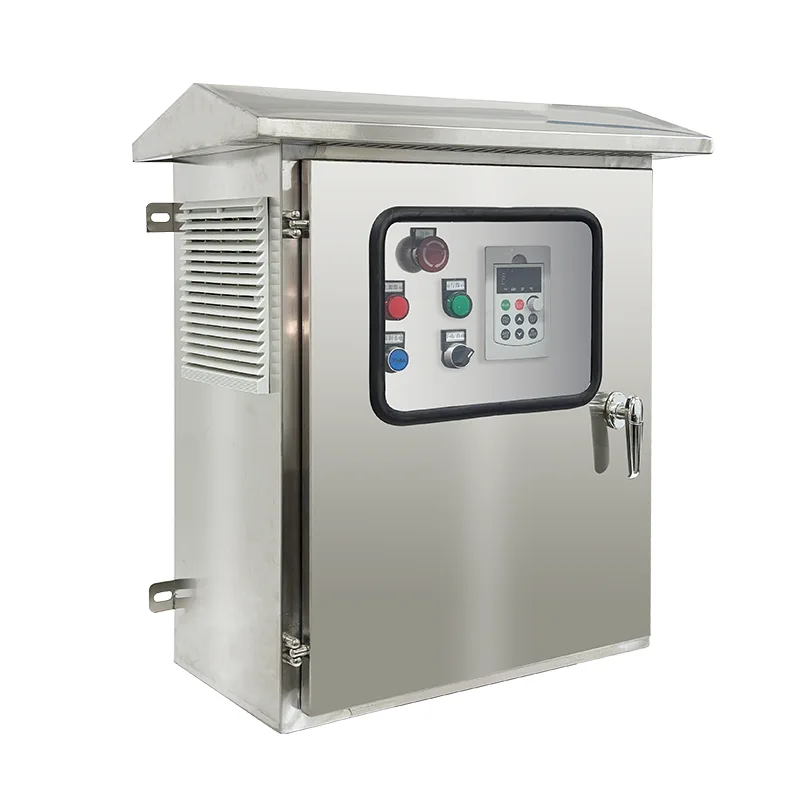
The standard MCC enclosure is fabricated from 2.0mm galvanised steel sheet with a powder-coated finish, achieving IP42 protection suitable for indoor electrical rooms. For dusty industrial environments — mines, cement plants, wood processing — IP54 or IP55 enclosures with filtered ventilation or air-to-air heat exchangers manage internal cooling while excluding airborne particulates. For outdoor installations, IP65 enclosures with thermostatically controlled anti-condensation heaters, rain canopies, and stainless steel hardware are available. In tropical environments, conformally coated PCBs and sealed connectors prevent moisture-induced tracking.
Every MCC Panel undergoes a defined factory acceptance test programme: busbar continuity and insulation resistance measurement; primary and secondary injection testing of protection relays; contactor, starter, and interlock functional simulation; withdrawable unit insertion and withdrawal testing; and communication network verification. A full FAT report is delivered with each MCC, together with single-line diagrams, layout drawings, and operation manuals. The MCC is designed, manufactured, and tested to IEC 61439-1/2, with CE marking and optional UL, UKCA, or other regional certifications.
The factory-engineered MCC Panel solution was selected for its proven ability to meet all requirements:
● Standardised withdrawable starter units (up to 250A) allowed rapid replacement of any motor starter without de-energising the entire MCC section
● Type 2 co-ordinated motor protection ensured that motor short-circuit faults would be cleared without starter component damage
● The 65kA-rated busbar system with arc-fault containment and Form 3 internal segregation provided the required safety level
● Intelligent motor management relays with Profibus DP communication in every starter unit transmitted real-time motor data to the SCADA — current, power, run hours, number of starts, thermal capacity used, and energy consumption — enabling predictive maintenance scheduling
● The multi-section line-up integrated air circuit breaker incomers, VFD sections for the aeration blowers, soft-starter sections for large pumps, and standard withdrawable starter sections for general motor loads — all within a common busbar system
Q1: What is the difference between an Solar Pump Control System and a standard distribution board?
A distribution board primarily distributes power to final circuits with fuses or circuit breakers but does not typically integrate motor starting or control. A Motor Control Centre combines motor starters (contactors, overloads, and drives), motor protection, and control intelligence in a single structured assembly — each functional unit is designed specifically for a motor load, not just a generic circuit. MCCs also include withdrawable unit capability, busbar segregation, and comprehensive motor management communication features not found in distribution boards.
Q2: How many motors can one Solar Pump Control System accommodate?
The number depends on section count and unit size. A single vertical section typically accommodates 4 to 12 motor starter units depending on their power rating. A multi-section MCC line-up can accommodate 50, 100, or more motors. Our application engineers will optimise the layout based on your motor list and site constraints.
Q3: What is the advantage of withdrawable units over fixed units?
Withdrawable (drawer-type) units allow a faulty starter to be isolated, physically withdrawn from the MCC, and replaced with a spare — all within minutes and without de-energising the entire MCC section. The main busbars remain live and other motor circuits continue operating. This is critical for continuous process industries where unplanned downtime on one motor must not cascade. Fixed units are lower cost but require the MCC section to be de-energised for starter replacement.
Q4: What do Form 2, Form 3, and Form 4 segregation mean?
These refer to the degree of internal compartmentalisation per IEC 61439-1/2. Form 2 separates functional units from busbars. Form 3 adds separation between individual functional units. Form 4 additionally separates terminals from each other and from other functional units. Higher forms provide greater safety during maintenance and contain arc faults more effectively, but cost more. We will recommend the appropriate form based on your operational and maintenance philosophy.
Q5: What short-circuit rating do I need for my MCC?
This is determined by the prospective fault current at the point where the MCC connects, which depends on the upstream transformer kVA rating, impedance, and cable impedance. Typical industrial installations require 50kA or 65kA at 400V. Power station and large process plant auxiliary boards may require 80kA or 100kA. We will analyse your system data and specify the correct rating.
Q6: How does the MCC communicate with our DCS or SCADA system?
Each motor starter unit or group of units includes a communication interface — typically Profibus DP, Profinet, Modbus RTU/TCP, or Ethernet/IP — that connects to your plant control network. Motor status (running, stopped, tripped), current, energy, and diagnostic data are transmitted continuously. The DCS can remotely start/stop motors and receive alarm notification.
Q7: Can the MCC be extended in the future?
Yes. The MCC is designed for extensibility at either end of the line-up. We recommend including spare vertical sections or spare unit slots in the initial order if future motor additions are planned. Extending an existing MCC requires matching the original busbar rating and design, so retaining the original manufacturer is important for compatibility.
Q8: What maintenance does an MCC Panel require?
Recommended maintenance includes: annual thermal imaging survey of busbar joints and termination points; functional testing of withdrawable unit interlocks and shutter mechanisms; verification of protection relay settings and trip functions; cleaning of ventilation filters; and inspection of door seals and gaskets. A detailed maintenance schedule is provided in the operation manual.
Address
No. 3788, Liujiang Road, Liushi Town, Yueqing City, Wenzhou City, Zhejiang Province, China
Tel
If you have any enquiry about quotation or cooperation, please feel free to email us at sanchia@csivei.com or use the following inquiry form.Our sales representative will contact you within 24 hours. Thank you for your interest in our products.
WhatsApp:8615705777705