Products
Constant Pressure Water Supply Control Cabinet
  • Constant Pressure Water Supply Control CabinetConstant Pressure Water Supply Control Cabinet

Constant Pressure Water Supply Control Cabinet

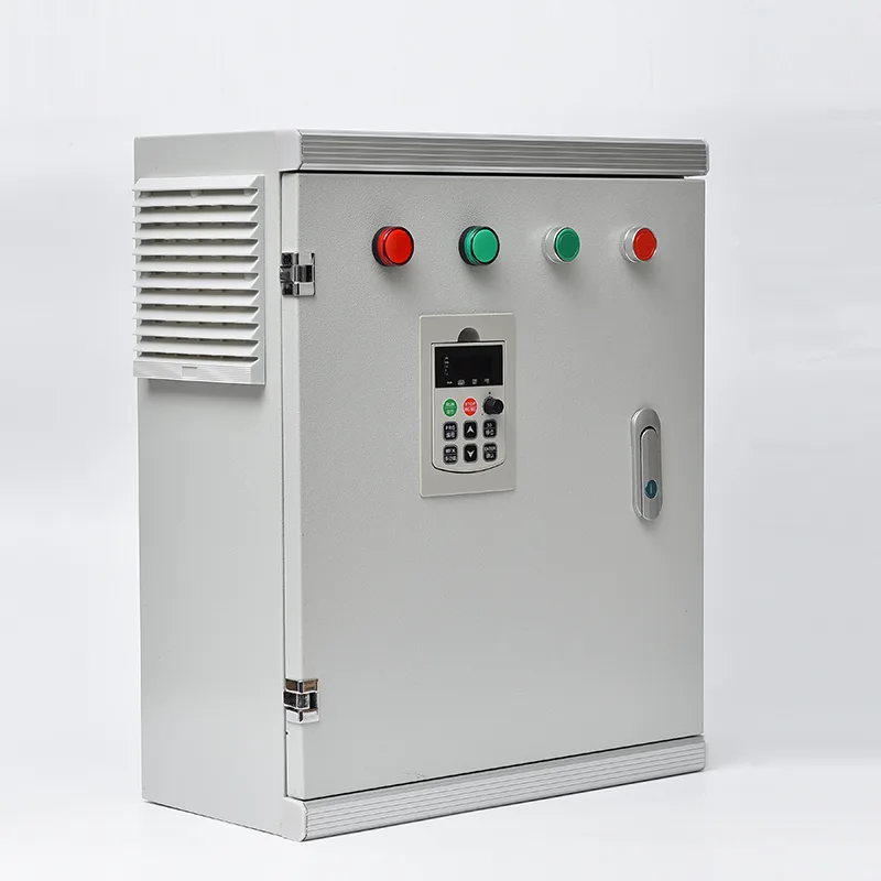
As a dedicated electrical control equipment manufacturer and supplier from China, our factory delivers the Constant Pressure Water Supply Control Cabinet — an integrated pump control enclosure that maintains stable water pressure through VFD speed regulation and PID closed-loop control. By automatically adjusting pump speed to match real-time demand, it eliminates the need for elevated tanks and throttle valves while reducing energy consumption. Backed by in-house engineering and certified production, we provide a complete constant pressure control solution for municipal, commercial, industrial, and agricultural water supply.

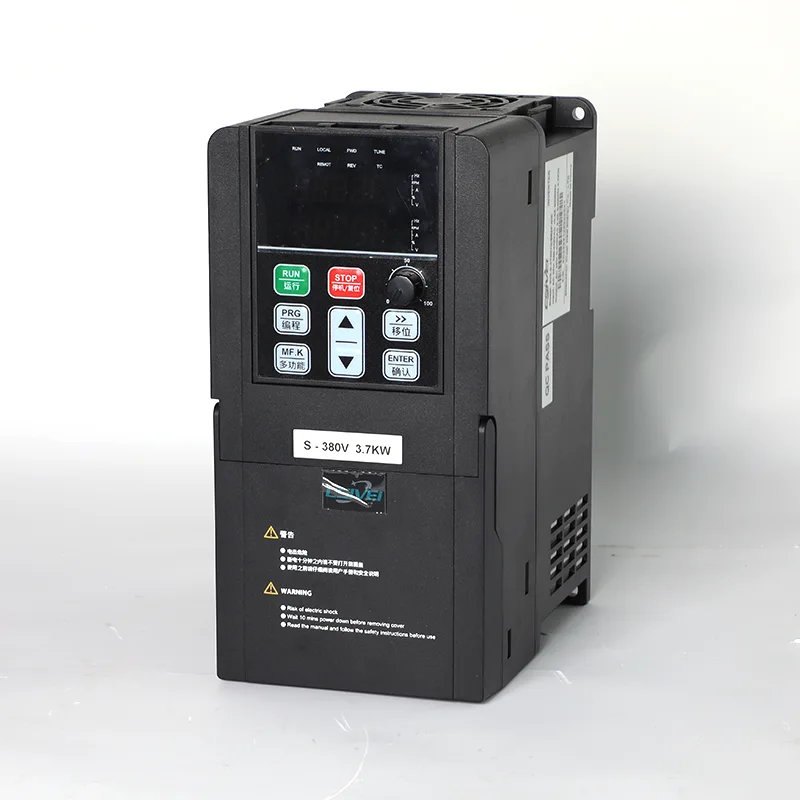
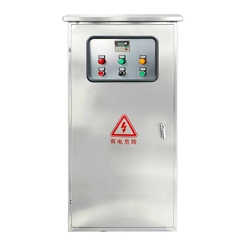
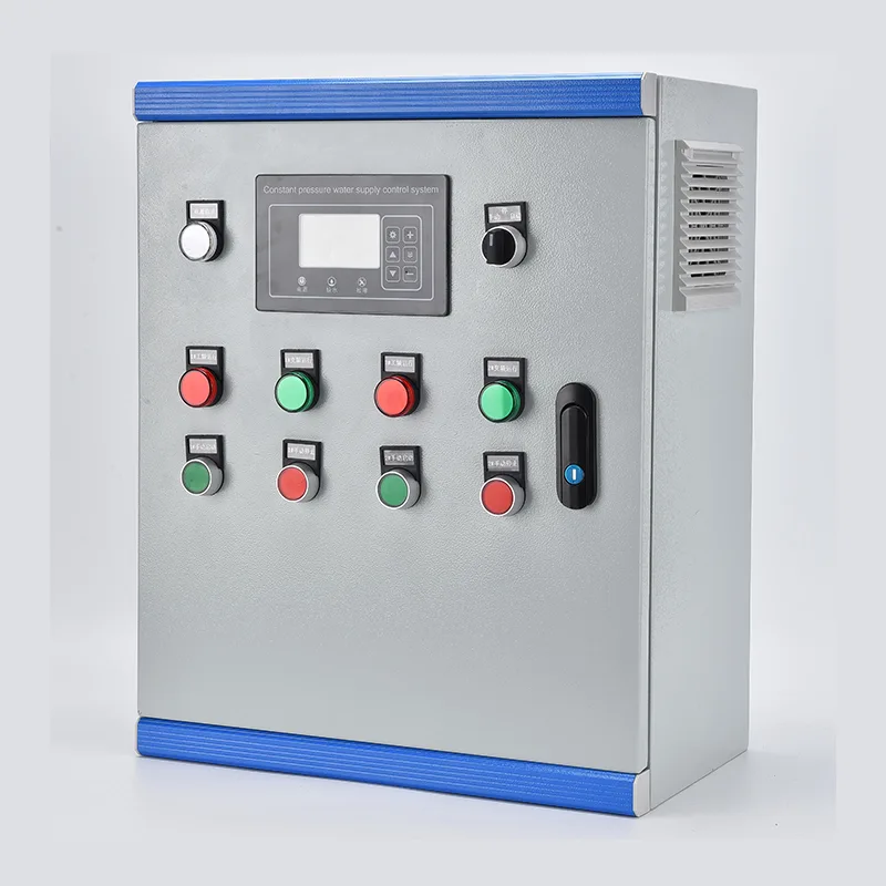
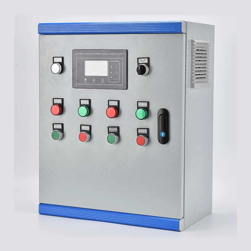
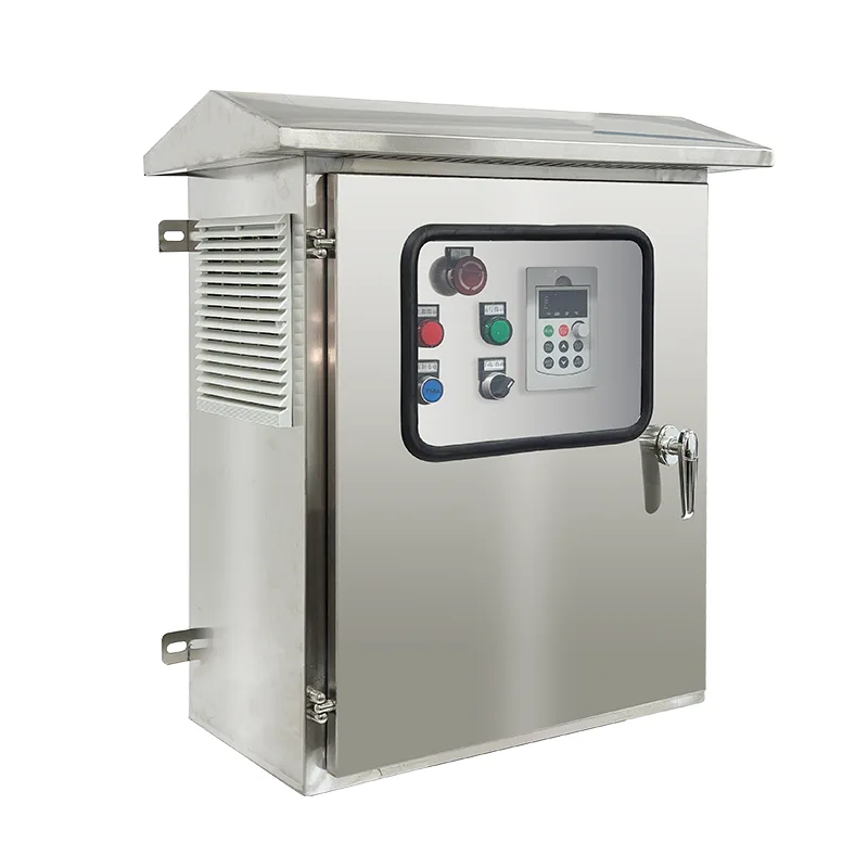
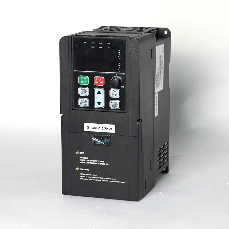
The Constant Pressure Water Supply Control Cabinet integrates a VFD, PLC or dedicated pump controller, incoming circuit breakers, output contactors per pump, control transformer, and pressure transmitter interface into a single floor-standing enclosure. Power ratings span 0.75 kW to 400 kW at 380–480 V three-phase. A pressure sensor on the main header feeds a 4–20 mA signal to the controller, which continuously compares actual pressure against the user-defined setpoint and adjusts VFD output frequency via a PID loop to maintain regulation within ±0.02 MPa. In multi-pump systems, the lead pump operates under VFD control while lag pumps are sequentially started or shed as demand fluctuates. Duty rotation balances run hours across all pumps. Protection covers dry-run, overload, phase loss, short circuit, and overpressure. A door-mounted HMI touchscreen displays system pressure, pump status, frequency, fault logs, and energy data. Communication via Modbus RTU/TCP or optional 4G cloud gateway enables remote monitoring and SCADA integration. The enclosure is fabricated from galvanised steel with powder coating, rated IP54 standard or up to IP65 for outdoor use.


Ideal Applications

Where water pressure must remain consistent despite changing demand, the Constant Pressure Water Supply Control Cabinet replaces gravity storage and fixed-speed pumping with automated, demand-responsive control.


Municipal Water Supply & Booster Stations

Urban water networks experience wide pressure swings between peak hours and overnight low-flow periods. The cabinet maintains constant pressure at designated network points by modulating pump speed and staging, eliminating the dips and surges that stress pipe joints and generate service complaints. For booster stations along long transmission mains, the PID loop adapts to changing upstream pressure and variable downstream offtake.


High-Rise Residential & Commercial Buildings

Apartment towers, hotels, and office blocks need reliable pressure on upper floors. A constant pressure cabinet with multiple vertical multi-stage pumps automatically adjusts output to match occupancy-based demand — lower at midday, higher during morning and evening peaks. The system removes the need for bulky roof tanks along with their structural load, legionella risk, and maintenance access requirements.


Industrial Process & Cooling Water

Manufacturing plants, food processing facilities, and power stations require process water at tightly controlled pressure. The cabinet supplies cooling tower makeup, washdown lines, boiler feed, and production water circuits with regulation accuracy suited to process needs. VFD-based control eliminates the energy waste and valve wear associated with throttling.


Agricultural Irrigation

Large-scale drip, sprinkler, and centre-pivot systems need variable flow at stable pressure across field zones with different emitter characteristics. The cabinet handles multiple pump configurations, including submersible borehole and horizontal booster pumps, automatically matching output to the number of open irrigation zones. Built-in dry-run protection safeguards pumps during source water level changes.


Rural & Community Water Supply

Village systems and remote settlements benefit from automated pressure management that replaces manual pump operation. Integrated with a storage tank level sensor, the cabinet starts and stops automatically to maintain tank fill while delivering constant pressure to consumers. Remote monitoring via 4G lets a single operator manage multiple scattered stations from a mobile phone or central SCADA.


Hotel, Resort & Hospitality

Resorts and leisure facilities with buildings spread across a site need uniform pressure for guest rooms, kitchens, laundry, and landscaping. The cabinet manages multiple pumps to meet peak morning and evening demand while reducing energy during off-peak hours, with the system largely in sleep mode overnight.


Technical Deep Dive

The Constant Pressure Water Supply Control Cabinet combines VFD speed control, PLC-based pump sequencing, and comprehensive protection into a single factory-assembled enclosure, delivering autonomous pressure management for single-pump to multi-pump installations.


PID Closed-Loop Pressure Regulation

A pressure transmitter on the main header pipe converts water pressure into a 4–20 mA analogue signal. The controller runs a digital PID algorithm: proportional gain determines how aggressively the system responds to pressure deviation, integral time eliminates steady-state offset, and derivative damping suppresses overshoot during sudden flow changes. The PID output directly sets the VFD frequency reference, adjusting pump speed to match demand in real time. Typical regulation accuracy holds within ±0.02 MPa once tuned to the specific system characteristics — pipe length, pump curve, and pressure vessel volume.


Multi-Pump Sequencing Logic

When demand exceeds the capacity of a single VFD-driven pump, the controller stages additional pumps into operation. The lead pump runs under VFD control. If it reaches maximum frequency and pressure still falls below setpoint, the controller transfers this pump to fixed-speed operation via its bypass contactor and starts a lag pump under VFD control. As demand drops and the VFD reaches minimum frequency with pressure above setpoint, lag pumps are shed one by one and the lead pump returns to variable-speed control. This ensures only one pump runs at variable speed at any time while the others operate at fixed speed near their best efficiency point.


Duty Rotation and Equalisation

To distribute wear evenly, the controller rotates the lead pump designation based on cumulative run hours or start count. The pump with the lowest hours becomes the next lead when rotation triggers, which occurs at low-flow conditions to avoid pressure disruption. A pump taken offline for maintenance is locked out of the rotation via a digital input, and the controller reallocates duty across the remaining pumps.


Sleep, Wake, and Low-Flow Management

During zero-demand periods — overnight in commercial buildings, for example — the VFD eventually reaches its minimum frequency while pressure holds at setpoint. After a configurable delay, the controller enters sleep mode and stops all pumps. A small diaphragm tank maintains system pressure during sleep. When pressure decays to the wake threshold, the controller restarts the lead pump and ramps up to restore pressure. This cycle prevents pumps running against a closed valve for extended periods, saving energy and protecting the pump from overheating.


Pump Protection Suite

The controller provides pump-specific protections beyond standard motor overload. Dry-run detection uses either a digital input from a well level probe or motor undercurrent sensing. Overpressure trip with auto-reset prevents pipe damage if a valve closes suddenly. A rapid-cycle lockout limits the number of starts per hour to protect the motor windings. Phase loss and phase sequence monitoring prevent mechanical damage from reverse rotation. All trip events are time-stamped and stored in the fault log, with a configurable number of auto-reset attempts before lockout requires operator intervention.


VFD Drive Architecture

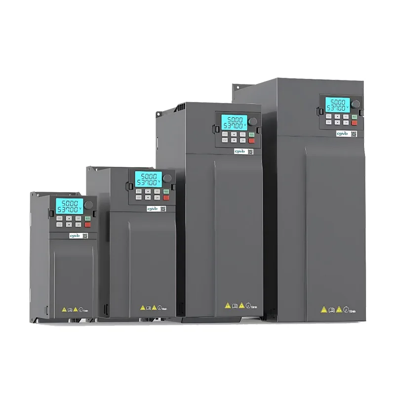
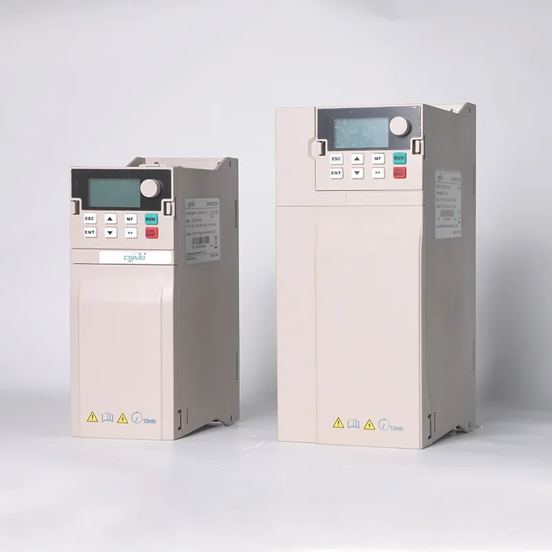
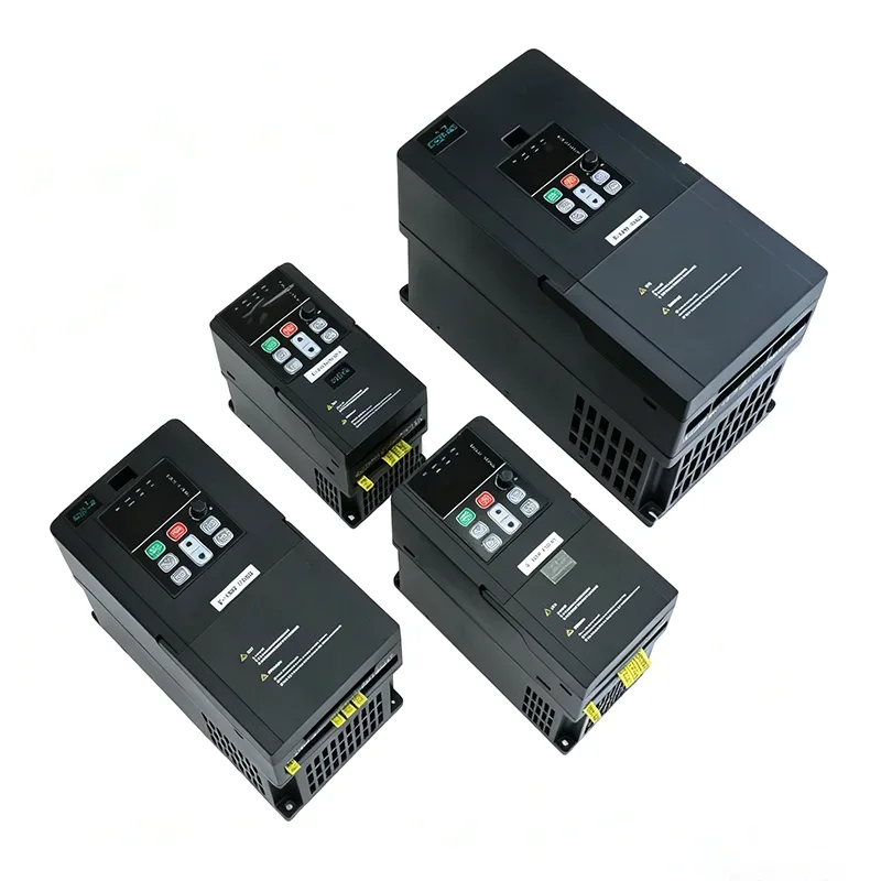
The VFD is selected for variable-torque pump duty with a 110% overload rating for 60 seconds. Flying-start capability enables seamless restart into a coasting pump without tripping on overcurrent. Skip-frequency programming avoids mechanical resonance bands. Automatic energy optimisation reduces motor magnetising current at light load, saving additional energy when the pump runs below full speed. A built-in DC link choke and RFI filter minimise harmonic current injection onto the supply.


HMI and Operator Interface

A door-mounted colour touchscreen provides real-time system pressure and setpoint, individual pump status, cumulative run hours and start count per pump, active alarms with fault history, and password-protected parameter access. Manual override control supports commissioning and maintenance activities.


Remote Monitoring and Communication

Standard RS485 Modbus RTU connects to site SCADA or telemetry equipment. An optional 4G or Ethernet cloud gateway enables remote access via web browser or smartphone app, delivering real-time pressure, pump status, energy consumption, and alarm push notifications. Operators can adjust pressure setpoints remotely for specific system requirements.


Enclosure and Environmental Construction

The floor-standing cabinet uses 1.5–2.0 mm galvanised steel sheet with UV-resistant powder coating. IP54 is standard for indoor pump rooms. IP55 or IP65 is available for outdoor and water-treatment environments. Filtered forced-air ventilation with thermostatic fan control maintains internal temperature within the VFD's operating range. For tropical or desert outdoor installations, a sunshade canopy and anti-condensation heater can be specified. Cable entry is through gland plates in the cabinet base. The cabinet is designed and constructed to IEC 61439-1/2, with all components CE-marked and regional certifications available.


Frequently Asked Questions

Q1: How does the cabinet maintain constant pressure?

A pressure sensor on the main water header continuously measures system pressure and sends a 4–20 mA signal to the controller. The controller's PID algorithm compares actual pressure against the user-set target. If pressure drops, it increases the VFD output frequency to speed up the pump. If pressure rises, it slows the pump. This closed-loop regulation runs continuously, typically holding pressure within ±0.02 MPa of the setpoint.


Q2: How many pumps can one Constant Pressure Water Supply Control Cabinet control?

Standard configurations support 1 to 6 pumps, with 2 or 3 pumps being the most common deployment. In multi-pump systems, a single VFD drives the variable-speed pump while additional pumps start at fixed speed as demand rises. All pump sequencing, alternation, and fault changeover logic is built into the controller.


Q3: What is the difference between this cabinet and installing separate VFDs on each pump?

The cabinet delivers a complete control system — pump sequencing logic, pressure PID loop, automatic alternation, fault changeover, sleep/wake function, and a single user interface — all pre-wired and factory-tested. Individual VFDs cannot co-ordinate multi-pump operation without significant external engineering.


Q4: Can the system work with or without a storage tank?

Both. In a tank-fill application, the controller maintains system pressure while a level sensor in the tank provides start/stop authority. In a direct main configuration, the controller maintains line pressure directly on the distribution piping, modulating pump speed to match consumer demand without any storage tank.


Q5: What pump types are compatible?

The cabinet controls standard three-phase induction motors used in submersible borehole pumps, vertical multi-stage pumps, horizontal end-suction centrifugal pumps, and inline booster pumps, across 380–480 V, 50/60 Hz. Permanent magnet motors can also be driven with compatible VFDs.


Q6: What power range is available?

Standard configurations cover 0.75 kW to 400 kW. Cabinet sizing is based on the number of pumps, each pump's motor full-load current, and the site fault level. Our engineers will select the VFD, contactors, circuit breakers, and busbar system from your pump data.


Q7: What remote monitoring options are available?

Standard RS485 Modbus RTU connects to site SCADA. Optional 4G or Ethernet gateways link to a cloud platform, providing access via web browser or smartphone app to real-time pressure, pump status, energy consumption, fault alarms, and historical data. SMS or app push notifications alert operators to faults.


Q8: What maintenance does the cabinet require?

Monthly inspection of door seals and ventilation filters. Quarterly check of power terminations. Annual functional test of safety devices and alternation logic. The VFD cooling fans and DC link capacitors have a service life of 5–10 years and are replaceable. The pressure transmitter should be calibrated annually.


Q9: How does this system save energy compared to traditional pumping?

A constant-speed pump with a throttling valve wastes energy pumping against an artificial restriction. The VFD matches pump speed directly to demand. Because pump power scales with the cube of speed, a pump at 80% speed draws roughly 50% of full-speed energy. With sleep mode during zero-demand periods, installations typically achieve 20% to 40% energy reduction.


A Municipal Secondary Water Supply Upgrade — High-Rise Residential District

Background

A municipal water authority in a major Asian city managed over 80 secondary water supply booster stations serving high-rise residential communities. Each station supplied 200 to 800 apartments across towers from 18 to 35 floors. The existing equipment was ageing — some stations used roof tanks with float-valve refill, others used fixed-speed pump sets with pressure-reducing valves. The city government mandated an upgrade to improve pressure quality, remove roof tanks on public health grounds, and cut pumping energy consumption.


The Challenge

Each booster station served a tower with a distinct demand profile: sharp morning and evening peaks, moderate daytime demand, and near-zero flow overnight. The existing fixed-speed pumps ran at full capacity regardless of demand, bleeding excess pressure through pressure-reducing valves. This wasted substantial energy while generating heat and noise in the pump rooms. Roof tanks needed to be removed to meet new health regulations, and the authority required all new stations to report data to a central SCADA platform. Physical space was also tight — most pump rooms were retrofitted into basement areas with limited ceiling height and restricted access.


Why Choose Constant Pressure Water Supply Control Cabinet?

After a successful pilot at three stations, the authority selected factory-engineered constant pressure cabinets. A single enclosure housed the VFD, controller, output contactors for three vertical multi-stage pumps, pressure interface, and HMI touchscreen — matching the footprint of the old panel. PID pressure control allowed the pressure-reducing valves to be removed entirely. The lead pump varied speed to match demand, with additional pumps staging as needed. Overnight, the system slept, pressure held by a small diaphragm vessel.


Water pressure at top-floor apartments stabilised at the regulatory minimum regardless of demand, without the excess pressure at lower floors that the old system caused. Energy consumption was metered per station and transmitted to the authority's SCADA over Modbus, giving operators real-time visibility and the ability to adjust pressure setpoints remotely for each tower's specific height.


Deployment

Thirty-two constant pressure cabinets were installed across the first phase over 18 months. Each cabinet was pre-loaded with pump data and pressure setpoints matched to the specific tower. On-site commissioning connected mains supply, pump motor cables, and the pressure transmitter — typically completed in one day per station.


Results

●  Pressure complaints from top-floor residents across the 32 communities dropped to zero within three months of commissioning.

●  Pump energy consumption fell by an average of 35% compared to the previous fixed-speed baseline, exceeding the authority's 25% target.

●  Roof tanks were decommissioned and removed, eliminating associated maintenance and water quality compliance costs.

●  A two-person operations team now manages all 32 stations remotely from the central SCADA.

●  The authority has standardised the constant pressure cabinet for the remaining 50 stations, with phase two currently underway.


Constant Pressure Water Supply Control Cabinet
Hot Tags: Constant Pressure Water Supply Control Cabinet
Send Inquiry
Contact Info

If you have any enquiry about quotation or cooperation, please feel free to email us at sanchia@csivei.com or use the following inquiry form.Our sales representative will contact you within 24 hours. Thank you for your interest in our products.


WhatsApp:8615705777705

Web:www.csiveivfd.com


X
We use cookies to offer you a better browsing experience, analyze site traffic and personalize content. By using this site, you agree to our use of cookies.Privacy Policy
RejectAccept